
AutoCAD®StructuralDetailing2011
GettingStartedwithAutoCAD®
StructuralDetailing,
Steelmodule
© 2010 Autodesk, Inc. All Rights Reserved. Except as otherwise permitted by Autodesk, Inc., this
publication, or parts thereof, may not be reproduced in any form, by any method, for any purpose.
Certain materials included in this publication are reprinted with the permission of the copyright
holder.
Disclaimer
THIS PUBLICATION AND THE INFORMATION CONTAINED HEREIN IS MADE AVAILABLE
BY AUTODESK, INC. “AS IS.” AUTODESK, INC. DISCLAIMS ALL WARRANTIES, EITHER
EXPRESS OR IMPLIED, INCLUDING BUT NOT LIMITED TO ANY IMPLIED WARRANTIES
OF MERCHANTABILITY OR FITNESS FOR A PARTICULAR PURPOSE REGARDING THESE
MATERIALS.
Trademarks
The following are registered trademarks of Autodesk, Inc., in the USA and/or other countries:
Autodesk Robot Structural Analysis, Autodesk Concrete Building Structures, Spreadsheet Calculator, ATC, AutoCAD,
Autodesk, Autodesk Inventor, Autodesk (logo), Buzzsaw,
Design Web Format, DWF, ViewCube, SteeringWheels, and Autodesk Revit.
All other brand names, product names or trademarks belong to their respective holders.
Third Party Software Program Credits
ACIS Copyright© 1989-2001 Spatial Corp. Portions Copyright© 2002 Autodesk, Inc.
Copyright© 1997 Microsoft Corporation. All rights reserved.
International CorrectSpell™ Spelling Correction System© 1995 by Lernout & Hauspie Speech
Products, N.V. All rights reserved.
InstallShield™ 3.0. Copyright© 1997 InstallShield Software Corporation. All rights reserved.
PANTONE® and other Pantone, Inc. trademarks are the property of Pantone, Inc.© Pantone, Inc.,
2002.
Portions Copyright© 1991-1996 Arthur D. Applegate. All rights reserved.
Portions relating to JPEG © Copyright 1991-1998 Thomas G. Lane. All rights reserved. Portions of
this software are based on the work of the Independent JPEG Group.
Portions relating to TIFF © Copyright 1997-1998 Sam Leffler. © Copyright 1991-1997 Silicon
Graphics, Inc. All rights reserved.
Government Use
Use, duplication, or disclosure by the U.S. Government is subject to restrictions as set forth in
FAR 12.212 (Commercial Computer Software-Restricted Rights) and DFAR 227.7202 (Rights in
Technical Data and Computer Software), as applicable.
Contents
GettingStartedGuide......................................................................................................................1
GettingStarted.............................................................................................................................1
ExploringtheUserInterface.........................................................................................................1
ProgramPreferences....................................................................................................................3
CreatingaSteelStructure.............................................................................................................4
CreatingaNewProject.............................................................................................................5
AddingWorkframes..................................................................................................................5
AddingColumns........................................................................................................................9
AddingBeams.........................................................................................................................12
AddingConnections................................................................................................................15
AddingBracing........................................................................................................................27
AddingPurlins.........................................................................................................................32
CreatingAssemblies....................................................................................................................35
Autopositioning..........................................................................................................................37
GeneratingDrawings..................................................................................................................38
GettingStartedGuide
ThankyouforchoosingAutoCAD®StructuralDetailing.TheSteelmoduleisatoolforgenerating
fabricationworkshopdocumentation,includingdrawingsandbillsofmaterials.Theexercisesin
thisguidegiveyouastartingpointforpreparationofyourownprojects.
GettingStarted
Before beginning the exercises, you need to install and register the software.
AutoCAD® Structural Detailing software comes with the AutoCAD® Revit® Structure
Suite.Thissoftwareisavailablefor32‐bitand64‐bitWindowssystems.
ExploringtheUserInterface
Open AutoCAD® Structural Detailing, Steel module, and take a minute to view the
differentareasoftheinterface.
Ribbon
At the top of the interface is the standard Microsoft® Windows® element‐ribbon.
The ribbon is an element of the user interface which replaces the traditional menu
and toolbars and allows easy managing and adjusting the workspace. The ribbon
consists of several panels, grouped on tabs that are named by task or subject. The
ribbonpanelsincludemanyAutoCAD®StructuralDetailingcommandsthathavebeen
ontoolbarsandindialogssofar,suchasicons,drop‐downlists,sliders,textfieldsand
otherelementscharacteristicofagiventab.
NOTEItispossibletoswitchbetweenworkspaces(suchastheclassicworkspacewithoutthe
ribbon).Todoitfollowoneofthegivenmethods:
1 ClickManagehCustomizationh (UserInterface)hintheCustomizeUser
InterfacedialogboxselecttheCustomizetabandinASD/WorkspacesselectASDSteel
Classichright‐clickandselectSetcurrentfromthecontextmenuhclickApply
2 Click(atthebottomrightcornerofthescreen)andselect
ASDSteelClassic.
1
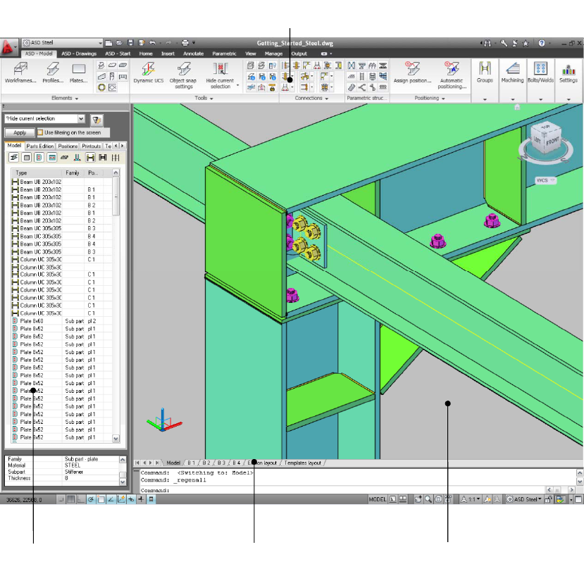
ObjectInspector
On the left is the Object Inspector, where you can manage AutoCAD® Structural
Detailing elements or objects. Object Inspector displays different lists of project
elements according to the design stage (modeling, positions, or printouts). You can
selectanelementorgroupofelements,modifytheirproperties,orfiltertheelements
thatdisplayintheInspector.Filtersalsoenableyoutodecreasethenumberofmodel
elementsdisplayedinthedrawingarea.
Model/LayoutTabBar
Atthebottomofthedrawingareaisthestandard AutoCAD®Model/LayoutTabBar.
There are 2 additional tabs defined – Edition Layout and Templates Layout. On the
Edition Layout tab, you can modify the drawings (documents) generated for the
structure elements or group of elements. The Templates Layout tab displays the
drawingtemplatesdefinedintheproject.
Ribbon
Model/DrawingArea
Model/LayoutTabBar
ObjectInspector
2
ProgramPreferences
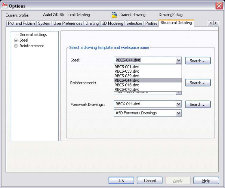
Preferences
ThePreferencesarelocatedinAutoCAD’sOptionsdialog.TheStructuralDetailingtab
letsyouselectthedefaultstarttemplateandworkspacenameforthe Steelmodule.
Thesoftwarehascountry‐specifictemplatesdefined(French‐RBCS‐033.dwt,English‐
RBCS‐044.dwt,Polish‐RBCS‐048.dwt,andRussian‐RBCS‐070.dwt).
Whenyouinstallthesoftwareandthedefaultdrawingtemplatesettingsareadjusted
automaticallytomatchtheregionalsettingsofyouroperatingsystem.
IntheOptionsdialog,youcanalsochangedisplaysettings,suchasthelevelofdetail
to display ina drawing. This can improve the performance ofthe software on many
computers.
Projectpreferences
Thesepreferences(material/profiledatabasesandstylesofdescriptions,dimensions,
andtables)arerelatedtoaparticulartemplateandproject.Usingthisdialog,youcan
adddatabasesorstylesatanytimeduringprojectdefinition.
3
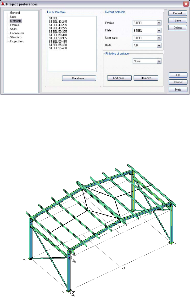
CreatingaSteelStructure
Inthislesson,youwillcreatethefollowingsteelstructuremodelusingthetools
availableintheSteelmoduleofAutoCAD®StructuralDetailing.
4
CreatingaNewProject
Inthisexercise,youwillcreateandnameaprojectinwhichyouwilldefineasteel
structure.
1 StarttheSteelmoduleofAutoCAD®StructuralDetailing:
ClickASD‐Starth(Steel).
2 ClickhNew.
3 IntheSelecttemplatedialog,selectRBCS‐044.dwt(Englishtemplate),
andclickOpen.
4 ClickhSave.
5 IntheSaveDrawingAsdialog:
• Navigatetothedesiredlocation.
• ForFilename,enterGetting_Started_Steel.
• ClickSave.
6 Proceedtothenextexercise,AddingWorkframes.
AddingWorkframes
Inthisexercise,youwillcreate3Dworkframesforthemainpartofthestructureand
fortheroof.
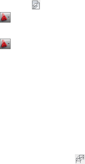
1 CreateWorkframe1forthemainpartofthestructure:
ClickASD‐ModelhElementsh (Workframes).
Alternatively,(forASDSteelClassicworkspace)clickSteelmenu
h
WorkframeshCreateWorkframe.
OntheSize/DivisiontaboftheWorkframedialog,acceptthedefault
valuesforWidthandHeight.ForLength,enter7500forsizeand1
fordivision.
5
OntheAxesdescriptionstab,selectHeight(Z),andthenselectUser
defined.
Click ,entertheaxisdescriptionvaluesasshown,andthenclick
OK.
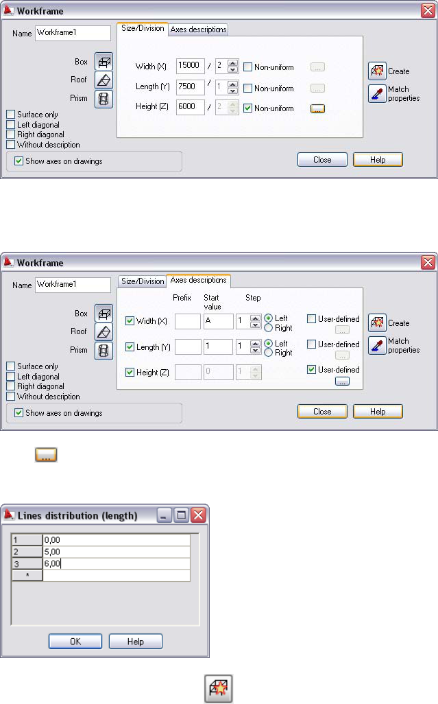
IntheWorkframedialog,click(Create),andindicateany2
pointsalongthedirectionoftheXaxis.
6

NOTEBesurethatOrthoModeison(pressF8toswitchiton/off).
2 CreateWorkframe2fortheroofofthestructure:
OntheSize/DivisiontaboftheWorkframedialog,acceptthedefault
valuesforWidthandLength.ForHeight,enter1000forsizeand1
fordivision.ForRidge,enter7500.
OntheAxesdescriptionstab,clearWidth(X)andLength(Y).For
Height(Z),belowUserdefined,click .
7
AddingColumns
Inthisexercise,youwillloadaprofilesdatabaseintotheproject,andthenaddnew
typesofprofiles.Youalsodefinecolumnsandplacethematspecificaxis
intersections.
1 LoadtheEUROprofilesdatabase:
ClickASD‐ModelhSettingsh(Projectpreferences).
Alternatively,clickSteelmenu
hProjectpreferences.
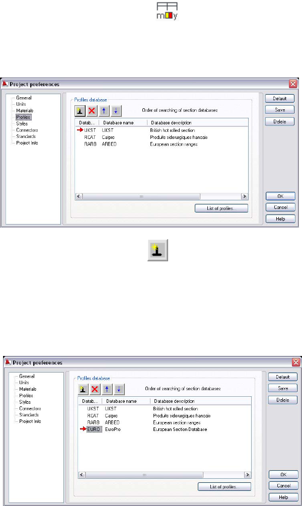
IntheleftpaneloftheProjectpreferencesdialog,selectProfiles.
UnderProfilesdatabase,click .
IntheDeclarationofsectiondatabasedialog,forDatabase,select
EURO,andclickOK.Thedatabasenowdisplaysonthelistofactive
databases.
IntheProjectpreferencesdialog,clickOKtoupdatethedatabase
list.
9

2 LoadadditionalprofilesfromtheEUROdatabase:
OpentheProjectpreferencesdialogagain.
Atthebottomofthedialog(Profilestab),clickListofprofiles.
IntheProfileListdialog,forDatabase,selectEURO.ForCAEType,
selectCAE90x9,andthenclickAdd>.Theselectedprofiledisplays
underListofselectedprofiles.
Usingthesamemethod,addthefollowingprofiles:IPE270,IPE330,
HEB120,andUPE200.
3 Definecolumns:
ClickASD‐ModelhElementsh(Profiles).
Alternatively,clickSteelmenu
hProfiles.
IntheProfiledialog,forProfile,selectIPE330,forMaterial,select
STEEL43‐245,andforFamily,selectColumn.
Click+90torotateasectionaboutitslongitudinalaxis(arotation
valuemayalsobeselectedfromthelistormaybeenteredintothe
Rotationfield).
10
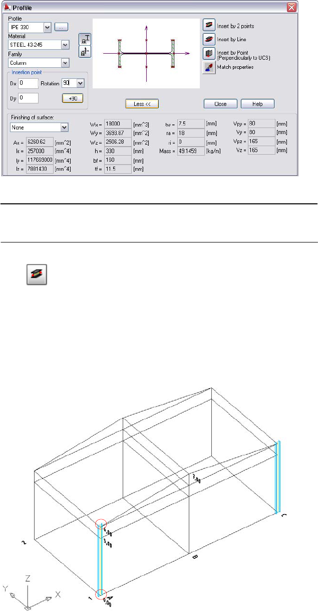
NOTEToseemoreinformationabouttheselectedsection(physical
properties,finishingsurfacetype),clickMore.
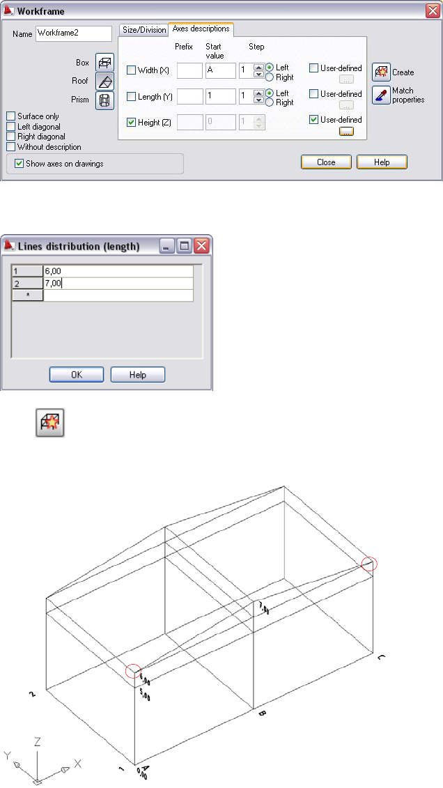
Click(Insertby2points),andthenclickinthedrawingareato
selectthepointsatA‐1onlevel0,00andA‐1onlevel6,00(circledin
redbelow).
Usingthesamemethod,insertacolumnatC‐1.
PressEnter,andthenclosethedialog.
5 Proceedtothenextexercise,AddingBeams.
11
AddingBeams
Inthisexercise,youwilldefinethebeamsofthe frameandplacethemonspecificaxes.You
thencopythewholeframefromaxis1toaxis2.
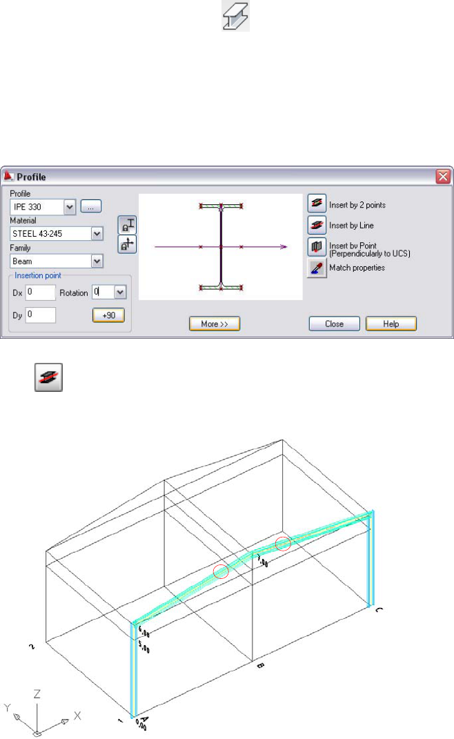
1 Defineframebeams:
ClickASD‐ModelhElementsh(Profiles).
Alternatively,clickSteelmenuhProfiles.
IntheProfiledialog,acceptthesettingsforProfileandMaterial,and
forFamily,selectBeam.
ForRotation,specify0.
Click(InsertbyLine),andthenselectthe2inclinedlinesinthe
frame(circledinredbelow)pressEnterandclosethedialog.
12
2 Copytheframe:
Selectallelementsoftheframe(bycrossingwindoworbyselecting
themintheObjectInspector).
Press(AutoCAD®Copycommand),andclickinthedrawingarea
toselectthepointsatB‐1thenatB‐2onlevel0,00(circledinred
below).
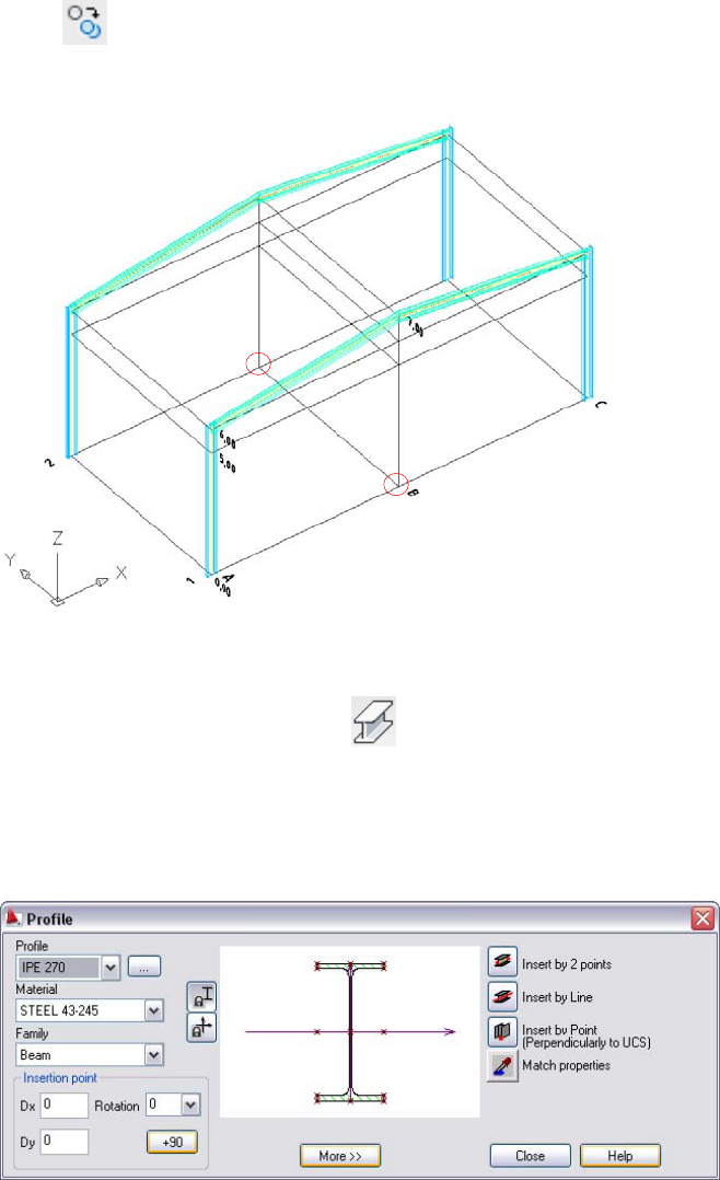
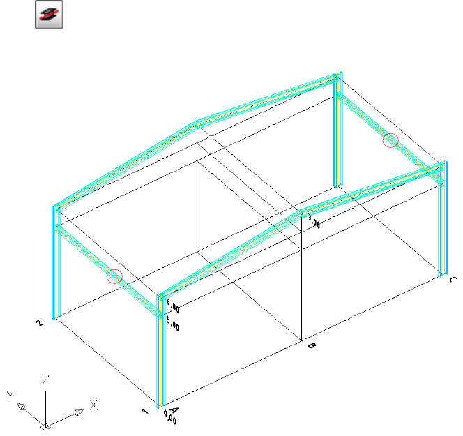
3 Definethebeamsconnectingtheframes:
ClickASD‐ModelhElementsh(Profiles).
Alternatively,clickSteelmenu
h
Profiles.
IntheProfiledialog,forProfile,selectIPE270(keepthecurrent
settingsforMaterialandFamily).
13
AddingConnections
Inthisexercise,youwilldefinefourtypesofelementconnections.Thenyoulearn
howtocopythedefinedconnection.
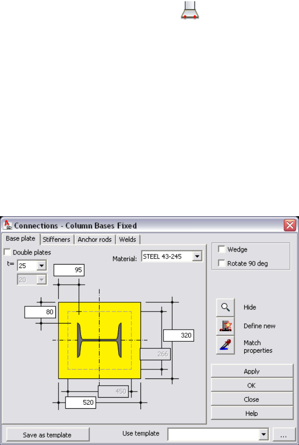
1 Definecolumnbaseconnection:
ClickASD‐ModelhConnectionsh (Columnbase‐fixed).
Alternatively,clickSteelmenuhConnectionshAutomatic
connectionsIhColumnbase‐fixed.
ClicktheintersectionofaxesAand1tospecifythebottompartof
thecolumn.
OntheBaseplatetaboftheConnectionsdialog,fort(thicknessof
thebaseplate),select25.
Forthewidthoftheplate(parameterontherightsideofthe
preview),enter320;forlength(bottomparameter),enter520.
ForMaterial,selectSTEEL43‐245.
OntheStiffenerstab,selectthefirst2groupsofstiffeners(those
alongtheflangesandthoseperpendiculartoflanges–appropriate
checkboxescircledinredbelow).
ForStiffenerheight(atthetopofthedialog),enter180.
15
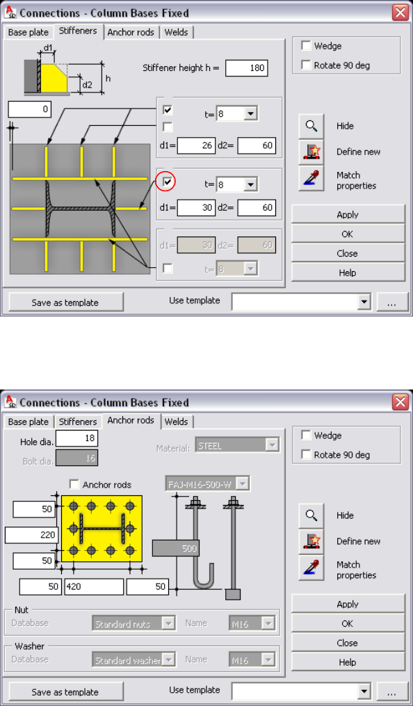
OntheAnchorrodstab,specifyboltspacing:fortheparameteron
theleft,enter220,andfortheparameteronthebottom,enter420.
OntheWeldstab,acceptthedefaultvaluesfortypeandsizeofthe
welds,andselectWedge(atthetoprightofthedialog).AWedge
tabdisplays.
16

OntheWedgetab,selectHEB120fromtheprofiledrop‐down.
ClickOKtogeneratetheconnectionandclosethedialog.
17
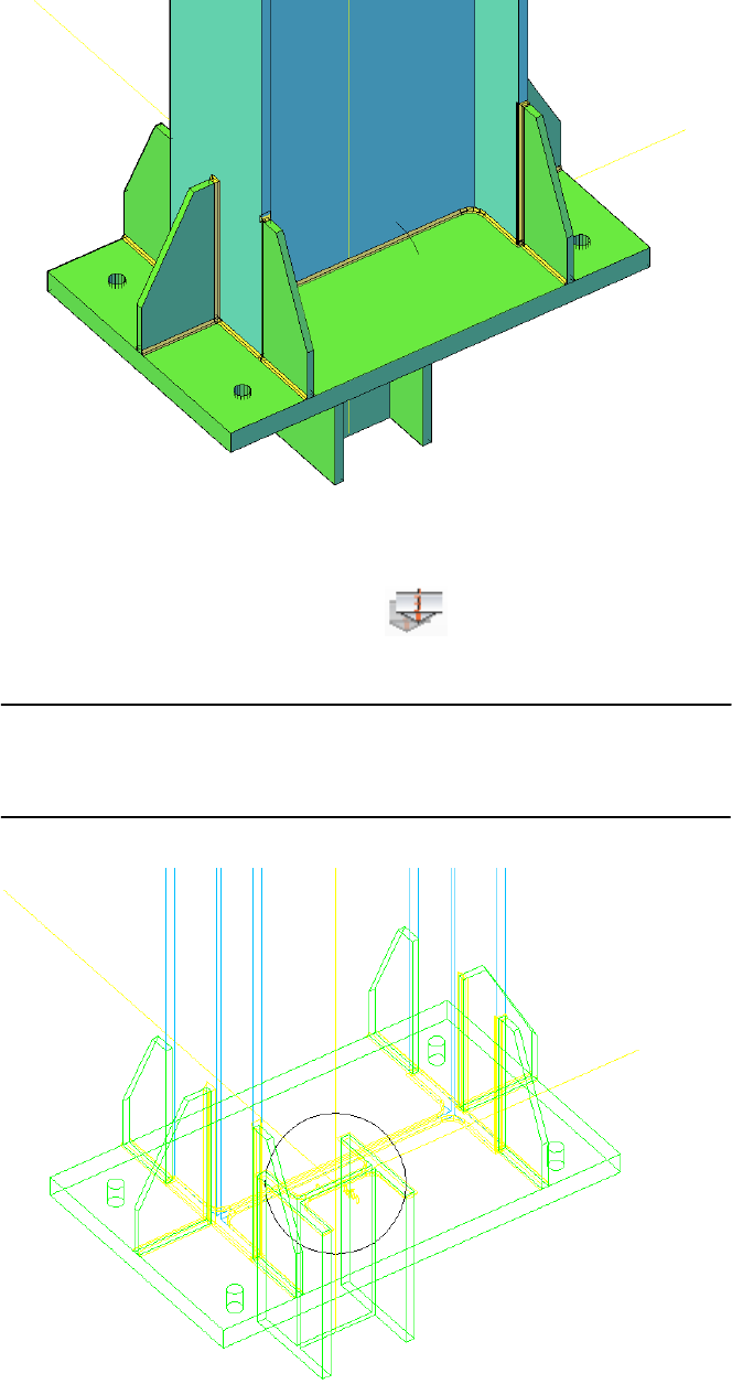
2 Copythecolumnbaseconnection:
ClickASD‐ModelhConnectionsh (Copyconnection).
Alternatively,clickSteelmenuhMachininghCopyconnection.
NOTEAllelementsgeneratedbyma cros(suchasconnectionsandspread
ofelements)arealsorepresentedbyacircle .Tomarkanyconnection,
clickontheappropriatecircle.
18
Clickthecirclethatrepresentsthegeneratedbaseofthecolumn
connection,andthenselectthebottompartsoftheremaining
columns.
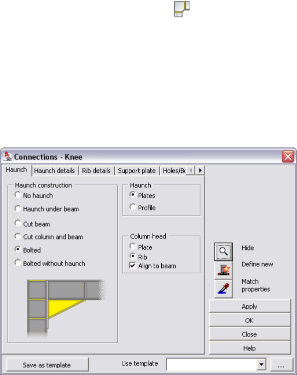
3 Define(column–beam)frameconnection:
ClickASD‐ModelhConnectionsh (Frameknee‐haunch).
Alternatively,clickSteelmenuhConnectionshAutomatic
connectionsIhFrameknees‐haunches.
ClicktheintersectionofaxesAand1,andthenclicktheinclined
beamontherightside(noticethatallrequiredactivitiesare
displayedonthecommandline).
OntheHaunchtab,forHaunchconstruction,selectBolted.
OntheHaunchdetailstab,forW(widthofthebeamendplate),
enter160.
Onthegraphicpreview,selectalltheribs(3inthecolumn,1inthe
beam).Additionally,selectFullheighttodefinethebeamribheight.
ForMaterial,selectSTEEL43‐245.
19
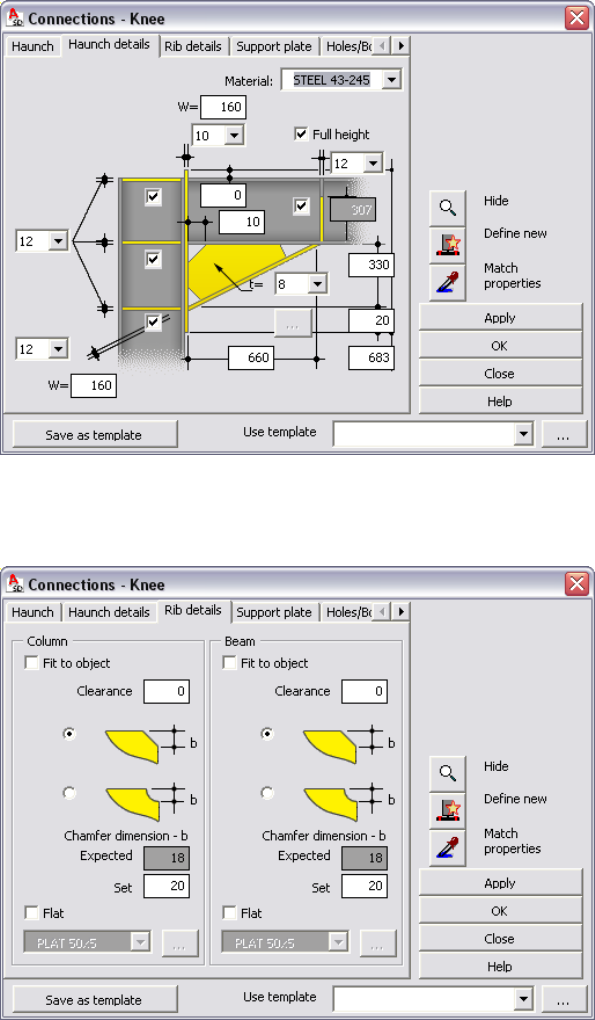
OntheRibdetailstab,underColumn,forChamferdimension–bh
Set,enter20.RepeatforthesamevalueunderBeam.
OntheHoles/Boltstab,forthedistanceofthefirstrowofboltsfrom
thetopedgeoftheplate,enter70.
ForRows,specify4.
Ontherightsideofthepreview,forthedistancevaluesinthe
center,enter200130200.
20

OntheWeldstab,acceptthedefaultvalues,andclickOKto
generateconnection.
4 Copytheframeconnection:
ClickASD‐ModelhConnectionsh (Copyconnection).
Alternatively,clickSteelmenu
hMachininghCopyconnection.
21
Clickthecirclethatrepresentstheframeconnection,andthen
selecttheremainingcolumnsandinclinedbeams.
NOTEBecauseconnectionsarecopiedonlyforelementsmeetingthe
samecriteria(elementtype,size,geometry),youdon’tneedtoselect
individualelements.Youcanselecttheentire structure,andtheproper
elementswillberecognizedautomatically.
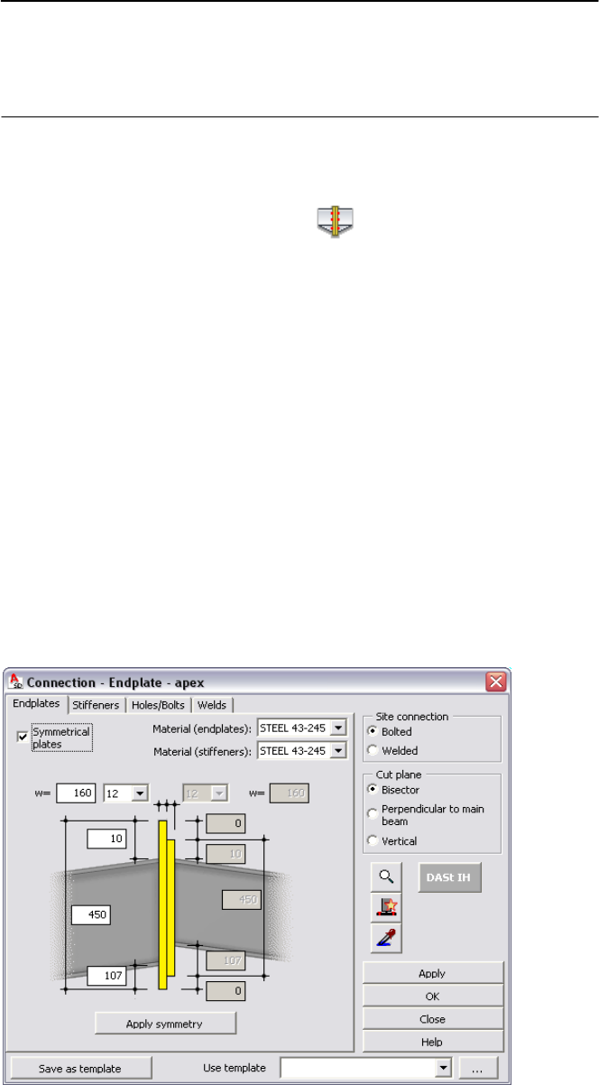
5 Defineinclinedbeamsconnection(inapex):
ClickASD‐ModelhConnectionsh (Endplate‐apex).
Alternatively,clickSteelmenu
hConnectionshAutomatic
connectionsIhEndplate‐Apex.
Inthedrawingarea,selectbothbeamsinaxis1.
OntheEndplatestaboftheConnectiondialog,selectSymmetrical
plates.
ForbothtypesofMaterial(endplatesandstiffeners),selectSTEEL
43‐245.
ForW(widthoftheendplate),enter160.
Inthegraphicalpreview,forthedimensionoftheplateabovethe
beam(topparameter),enter10.Forplateheight(center
parameter),enter450.
22
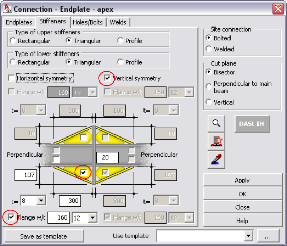
OntheStiffenerstab,selectVerticalsymmetry,andthenselectthe
elementstobegenerated:thestiffenerinthelowerleftquadrantof
thegraphicandFlangew/tinthelowerleftcornerofthedialog
(selectedelementscircledinredbelow).
Forthestiffenerdimension(parameterbelowtheselected
stiffener),enter300.
OntheHoles/Boltstab,forthehorizontalboltsspacingvalue,enter
100.
Forthedistanceofthefirstrowofboltsfromthetopedgeofthe
plate,enter70.
ForRows,specify3.
Ontherightsideofthepreview,forthedistancevaluesinthe
center,enter220100.
23

OntheWeldstab,acceptthedefaultvaluesfortypeandsizeofthe
welds,andthenclickOKtogeneratetheconnection.
6 Copytheconnectionofinclinedbeams:
ClickASD‐ModelhConnectionsh (Copyconnection).
Alternatively,clickSteelmenuhMachininghCopyconnection.
24
Inthedrawingarea,clickthecirclethatrepresentstheconnection
betweentheinclinedbeams.
Astheprofilestowhichconnectionistobeappliedselectthe
inclinedbeamsinthesecondframe.
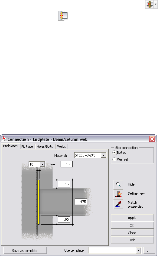
7 Definethebeam‐to‐columnconnection:
ClickASD‐ModelhConnectionshclickandholdtheicon ,
andontheflyout,click(Endplate‐beam/columnweb).
Alternatively,clickSteelmenuhConnectionshAutomatic
connectionsIhEndplate–beam/columnweb.
ClicktheintersectionofaxesAand2,andthenclickthebeamon
level5,0onaxisA.
OntheEndplatestab,fortheendplatethicknessvalue(parameter
onthetopleftcorner),select10,andthenforwidth(w),enter150.
ForMaterial,selectSTEEL43‐245.
Fortheplacementofplateabovethebeam,enter15.
Ontherightsideofthepreview,fortheheightvalueinthecenter,
enter475.
25
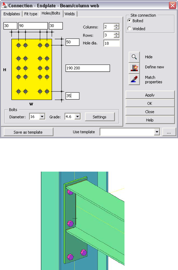
OntheFittypetab,acceptthedefaultsettings.
OntheHoles/Boltstab,forthehorizontalboltsspacingvalue,enter
90.
Forthedistanceofthefirstrowofboltsfromthetopedgeofthe
plate,enter50.
ForRows,specify3.
Ontherightsideofthepreview,forthedistancevaluesinthe
center,enter190200.
OntheWeldstab,acceptthedefaultvaluesfortypeandsizeofthe
welds,andthenclickOKtogeneratetheconnection.
26
8 Copythebeam‐to‐columnconnection:
ClickASD‐ModelhConnectionsh (Copyconnection).
Alternatively,clickSteelmenuhMachininghCopyconnection.
Clickthecirclethatrepresentsthebeam‐to‐columnconnection,and
thenselecttheremainingcolumnsandbeams.
9 Proceedtothenextexercise,AddingBracing.
AddingBracing
Inthisexercise,youwilldefinebracingusingoneoftheParametricStructuresmacros.
Todothis,youdrawauxiliarybracinglinesfirst,andthenusefilterstodecreasethe
numberofelementsthatdisplayonthescreen.
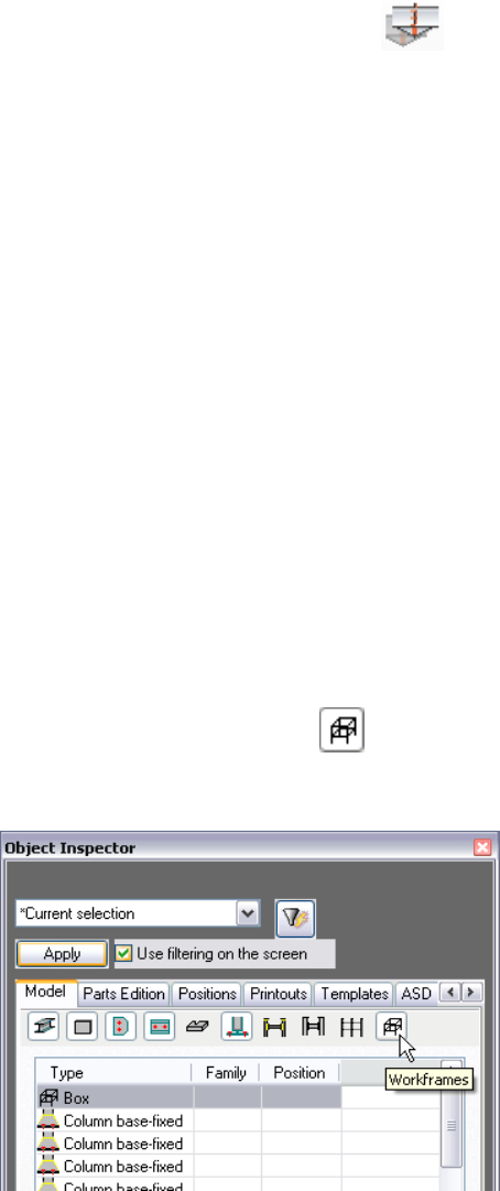
1 UsefiltertodisplayonlyWorkframe1onthescreen:
IntheObjectinspector,selectCurrentselectionfromtheFilter
menu(atthetopofthedialog),andthenselectUsefilteringonthe
screen.
OntheModeltab,verifythat(Workframes)ison.UnderType,
selectBox,andthenclickApply.
27
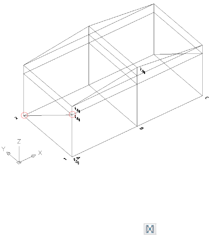
2 Definetheauxiliarybracingline:
ClickHomehLine,andthenclickinthedrawingareatoselectthe
pointsatA‐2onlevel0,00andA–1onlevel5,00(circledinred
below).
Usingthesamemethod,drawasimilarlineonaxisC.
Todisplayallelements,intheObjectinspector,selectAllObjects
fromtheFiltermenu,andclickApply.
3 Definebracing:
ClickASD‐Model
hParametricstructuresh (Bracing).
Alternatively,clickSteelmenuhParametricstructureshBracing.
Inthedrawingarea,selecttheauxiliarylineonaxisAasthefirst
auxiliarybracingline,andthenright‐clicktoautomaticallycreatethe
secondbracinglinebymirroringthefirst.Bydoingthis,youdefine
symmetricalbracing.
28
ClickcolumnontheintersectionofaxesAand2tospecifythe
locationofthefirstcolumn,andthenclickthecolumnonthe
intersectionofaxesAand1tospecifythelocationofthesecond
column.
Tospecifythehorizontallimitations,clickthebeamonlevel5,0and
axisA,andthenthebaseplatesofbothcolumnsselected
previously.Right‐clicktoaccepttheselection.
Tospecifytheverticallimitations,clickbothendplatesofthebeam
onlevel5,0andaxisA.
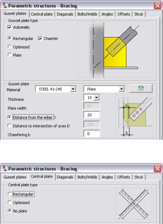
OntheGussetplatestab,underGussetplatetype,selectChamfer.
ForMaterial,selectSTEEL43‐245.
UnderGussetplate,forDistancefromtheedgeD,enter20.
OntheCentralplatetab,underCentralplatetype,selectNoplate.
29
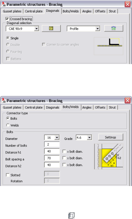
OntheDiagonalstab,forDiagonalselection,selectCAE90x9.
OntheBolts/Weldstab,forDistanceh1andDistanceh2,enter40.
ForBoltspacinga,enter70.
Acceptthedefaultvaluesontheremainingtabs,andclickOKto
generatethebracing.
ClickViewhViewshselect(Left)toseethegeneratedbracing
in2D.Alternatively,clickViewmenuh3DViewshLeft.
30
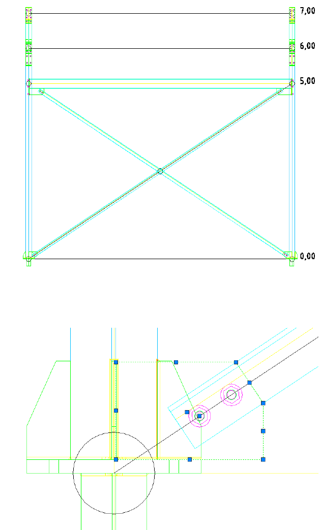
Zoomintothebottomleftcorner,andthenclickonthegusset
plate.
Toadjusttheshapeoftheplate,selectthegripatthebottomright
oftheplate,anddragittothebaseplatecorner(noticethatall
elementsgeneratedbymacroscanbeedited).
31
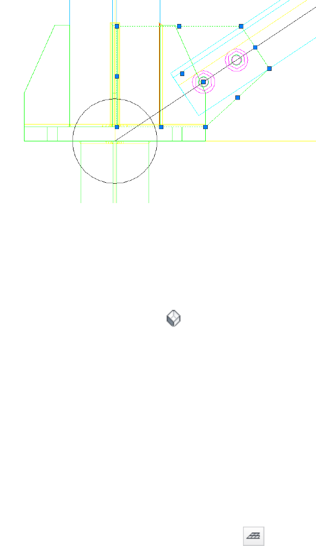
Usingthesamemethod,adjusttheshapeofthegussetplateinthe
secondcolumn.
Usingthemethodlearnedpreviously,generatebracingbetweenthe
columnsonaxisC(noticethatallsettingsintheBracingmacroare
savedfromthepreviousbracingdefinition).
ClickViewhViewshselect (SWIsometric).
Alternatively,clickViewmenuh3DViewshSWIsometric.
4 Proceedtothenextexercise,AddingPurlins.
AddingPurlins
Inthisexercise,youwilldefinepurlinsusingaParametricStructuresmacro.Youalso
defineadditionalbars(bracerods)betweenaxesofroofgirders.
1 Definepurlinspread:
ClickASD‐ModelhParametricstructuresh (PurlinSpread).
Alternatively,clickSteelmenuhParametricstructureshPurlin
Spread.
Inthedrawingarea,clicktheintersectionofaxesAand2onlevel
6,00todefinethestartpointofthefirstpurlinline.
Tospecifytheendpointofthefirstpurlin,clicktoselectthepointat
A‐1onthesamelevel.
32
ClickB‐1onlevel7,00tospecifythepointonthelastpurlin.
NOTEZoominasnecessarytoselectpointspre cisely.
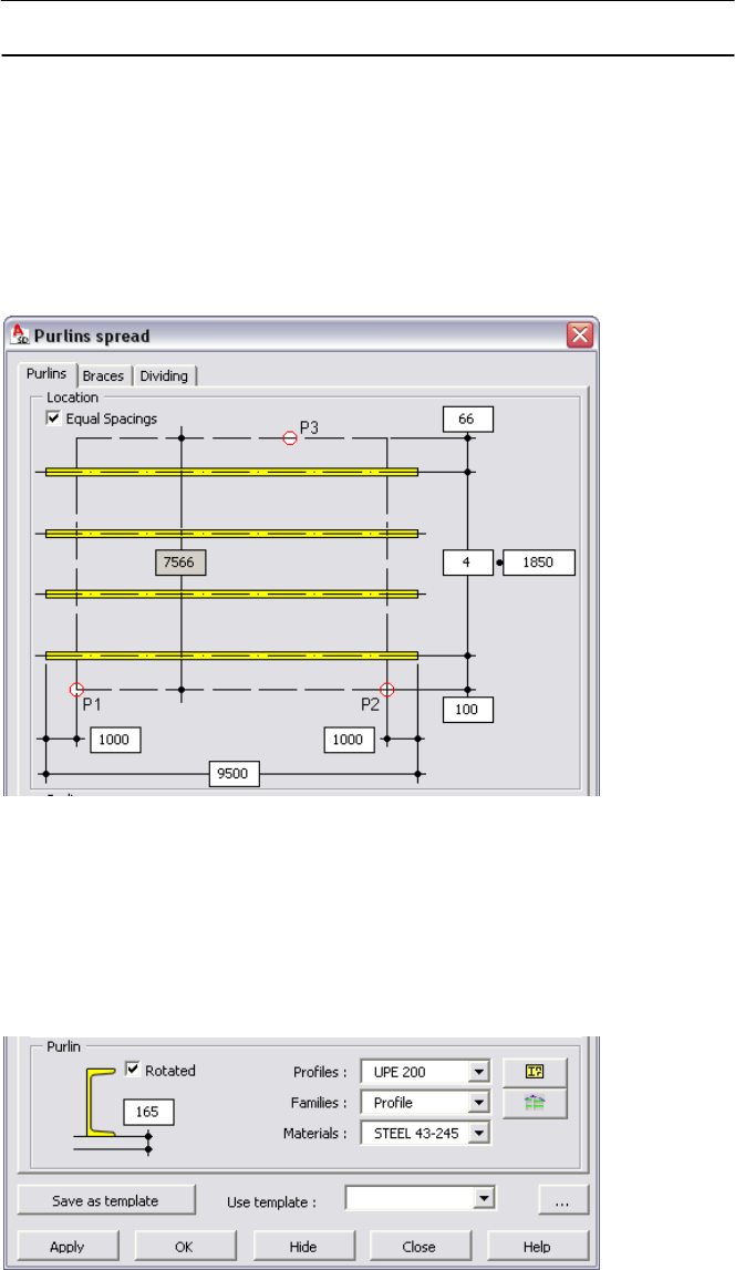
OnthePurlinstab,underLocation,forthenumberofpurlins(center
parameterontheright),enter4.
Forthespacingbetweenpurlins,enter1850.
ForthedistanceofthefirstpurlinfromlineP1–P2,enter100.
Forleftandrightoverhangvalues,enter1000.
UnderPurlin,forProfiles,selectUPE200,andforMaterials,select
STEEL43‐245.
SelectRotated(torotatethepurlin180°),andforthevertical
locationofthepurlin,enter165(halfofheightofsupportbeam
IPE330).
33
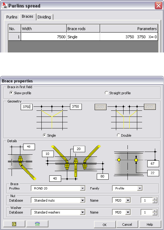
2 Definebracerods:
OntheBracestab,forBracerods,selectSingle.Acceptthedefault
valuesforWidth(columnspacing)andParameters(specifiesa
middlelocationforthebrace).
Selectthe1rowoftable,andclickProperties.
IntheBracepropertiesdialog,youcanchangepropertiessuchas
geometryanddetails.Inthiscase,acceptthedefaultparameter
values,andclickOK.
MakenochangesontheDividingtab(becauseofgeometryand
lengthofthepurlins,youwon’tdividethem),andclickOKto
generatepurlins.
34
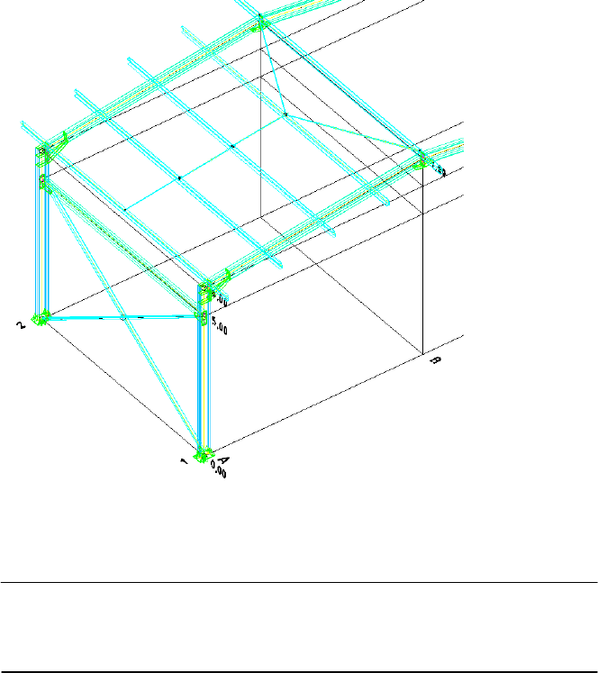
Usingthesamemethod,generatepurlinsontheremainingpartof
theroof.
NOTEToproperlyorientpurlins,selectthefollowingpoints:P1
(intersectionofaxesCand1onlevel6,00),P2(C‐2onlevel6,00),andthen
P3(B‐2onlevel7,00).
3 Proceedtothenextexercise,CreatingAssemblies.
CreatingAssemblies
Inthisexercise,youwilldefineassemblies.Anassemblyisdefinedaselementsjoined
togetherbyworkshopconnectors(boltsorwelds).Assembliesarecreatedinthe
projectautomaticallyormanually,dependingonprojectpreferences.Inthiscase
(usingaBritishtemplate),assembliesarecreatedautomatically,exceptthoseofloose
parts(singleelementswithoutanyadjoinedparts).Todefineassembliesfromloose
parts(purlins,bracings,andbracerods),firstyouchangesettingsintheProject
preferencesdialog.
35
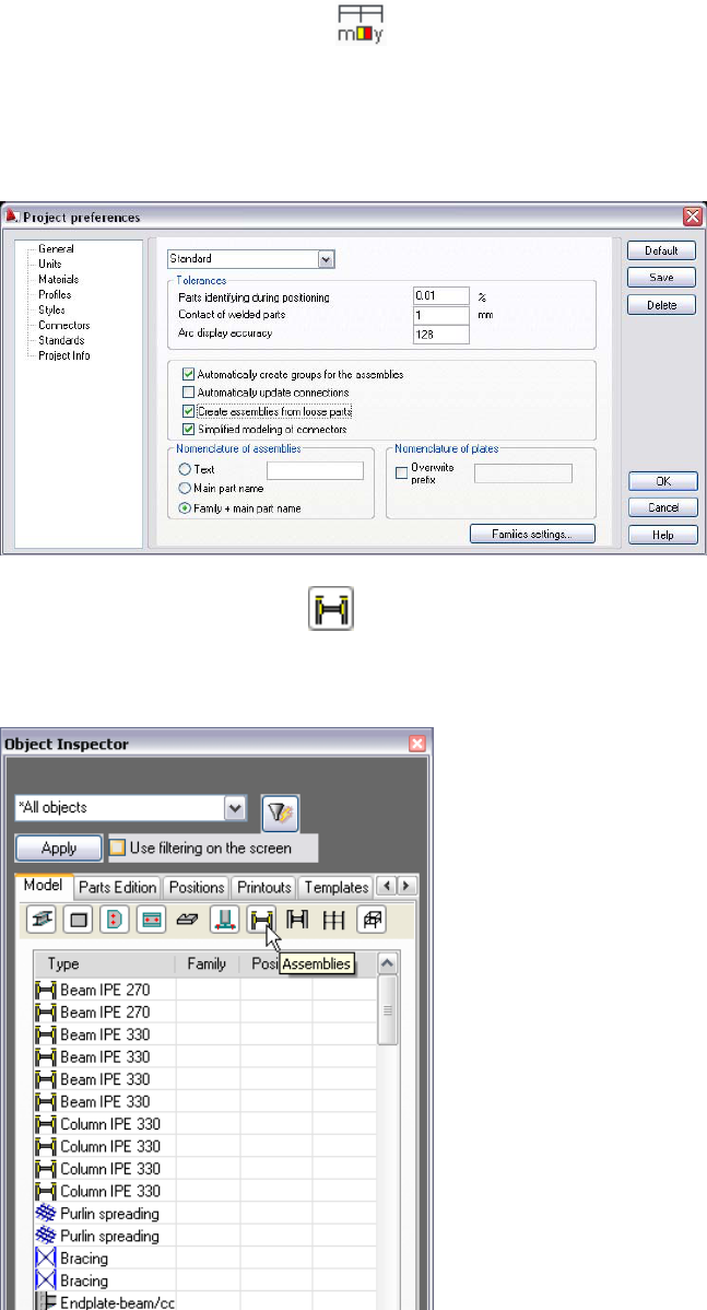
1 Createassembliesfromlooseparts:
ClickASD‐Model
hSettingsh(Projectpreferences).
Alternatively,clickSteelmenu
hProjectpreferences).
Inthemiddlepartofthedialog,selectCreateassembliesfromloose
parts,andthenclickOK.
IntheObjectInspector,click(Assemblies)todisplayall
assembliesgeneratedautomatically.Noticethatassembliesfrom
purlins,bracings,andbracerodswerenotcreated.
36
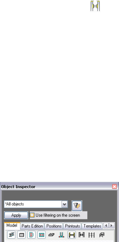
2 Defineassemblies:
ClickASD‐ModelhGroupsh(Groupassemblies).
Alternatively,clickSteelmenuhToolshGroupassemblies.
PressEntertoremoveassembliesalreadydefined.Noticethatnew
assembliesdisplayintheObjectInspector.
3 Proceedtothenextexercise,Autopositioning.
Autopositioning
Inthisexercise,youwillautomaticallyassignnames(positions)toallmodelelements.
Thisprocessisknownaspositioning.
1 OntheModeltaboftheObjectInspector,verifythatallelement
categoryiconsrequiredforpositioning(Profiles,Plates,PlateSubparts,
ProfileSubparts,andAssemblies)areselected.
2 Inthelistofprojectelements,selectanyelement,right‐click,andclick
Selectall.
3 Usingthesamemethod,clickAutoPositioning.
4 Acceptalldefaultsettings,andclickRun.Noticethataftertheprocessis
finished,namesofelementsdisplayunderPosition.
37

NOTEElementnamesarecreatedaccordingtoprefixesdefinedin
Families.Assembliesarenamedwithacapitalletter(forexample, beamis
definedwithB)andsuccessivenumbers(forexample,beamsB1,B2,B3,
andsoon).Singleelements(profilesandplates)arenamedthesameway
butwithlower‐caseletters(forexample,beamprofilesb1,b2,andplates
pl1,pl2).
5 Proceedtothenextexercise,GeneratingDrawings.
GeneratingDrawings
Inthisexercise,youwillautomaticallygenerateaworkshopdrawingforanassembly,
andwillmanuallycreateageneralarrangementdrawingforthewholestructure.You
canalsogenerateabillofmaterialsandaddittothedrawing.
1 Generateaworkshopdrawingforabeamassembly:
OnthePositionstaboftheObjectInspector,expandBeam.Select
B1,right‐click,andclickAutomaticDrawings.
38
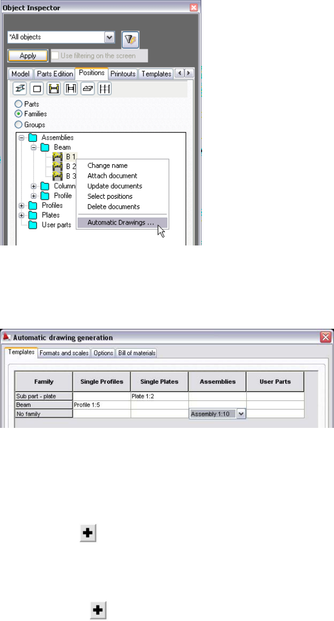
OntheTemplatestaboftheAutomaticdrawinggenerationdialog,
intheAssembliescolumnforNofamily,selectAssembly1:10.This
specifiesthedrawingtemplate(predefinedarrangementof
element’sviews).
OntheFormatsandscalestab,underArrangeviews,forMode,
selectAssemblyandparts(thiswillgenerate,ononedrawing,the
assemblyandallitsparts).
UnderFormatsandscales,forParttype,selectSingleProfiles.
ForScales,click ,andthenselect10.
Usingthesamemethod,specifyascaleof1/10fortheremaining
Parttypes.
ForFormats,click ,andaddA2ASD033.dwt(thesoftwarelists
onlyformatsofthepropersizeinrelationtothedrawingcontent).
39
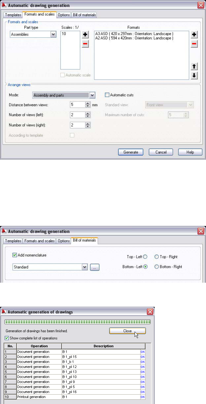
OntheOptionstab,acceptalldefaultsettings.
OntheBillofmaterialstab,selectAddnomenclature.
SelectBottom‐Leftasthelocationofthebillofmaterialstableon
thedrawing,andthenclickGenerate.
Afterthedrawingisgenerated,clickClose.
40
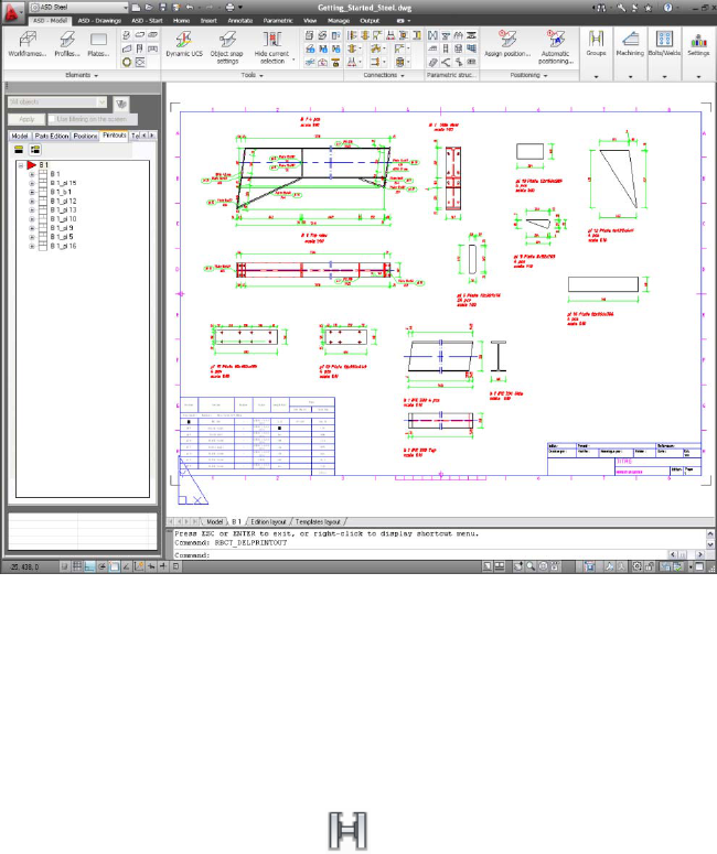
OnthePrintoutstaboftheObjectInspector,double‐clickB1to
displaythedrawing.(Becausethegeneratedviewsoftheassembly
anditspartsareonthedrawingasblocks,youcaneasilymodifythe
arrangement.)
2 DefineaSteelStructuregroupfromtheentirestructuremodel:
OntheLayout/ModelTabBar,clicktheModeltab.
OntheModeltaboftheObjectInspector,selectanyelementfrom
thelistofprojectelements,right‐click,andclickSelectall.
ClickASD‐Model
hGroupsh (Group).
Alternatively,clickSteelmenuhToolshGroup.
PressEntertoacceptthegrouptypeasaStandard,andthentype
SteelStructureasthegroupnameandpressEnter.
AcceptWCSasthegroupcoordinatesystem,andpressEnter.
3 CreateanisometricviewfortheSteelStructuregroup:
OnthePositionstaboftheObjectInspector,selectGroup.
SelectSteelStructure,right‐click,andclickAttachdocument.
41
IntheSelecttemplatedialog,youselectthetypeofdrawingthatwill
begeneratedfortheSteelStructuregroup(top/sideviewsor
isometricviews).Inthiscase,selectGroup‐arbitraryisometry1:50,
andclickOK.
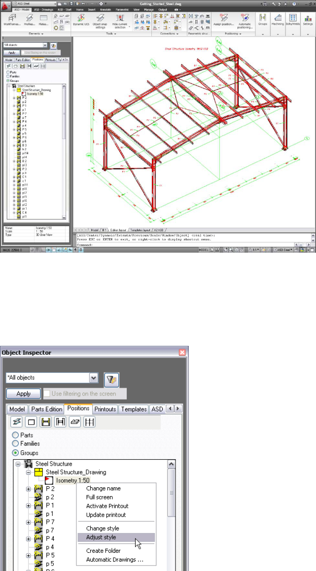
4 ModifytheSteelStructureisometricview:
IntheObjectInspector,expandSteelStructurehSteel
Structure_Drawing.SelectIsometry1.50,right‐click,andclickAdjust
style.
42
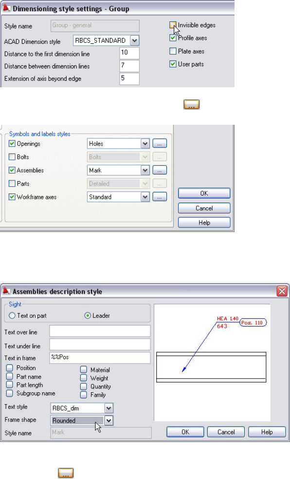
AtthetopleftoftheDimensioningstylesettings–Groupdialog,
clearInvisibleedgestoturnoffthedisplayofthatlinetype.
Atthebottomrightofthedialog,click(nexttoAssemblies).
IntheAssembliesdescriptionstyledialog,forFrameshape,select
Rounded,andthenclickOK.
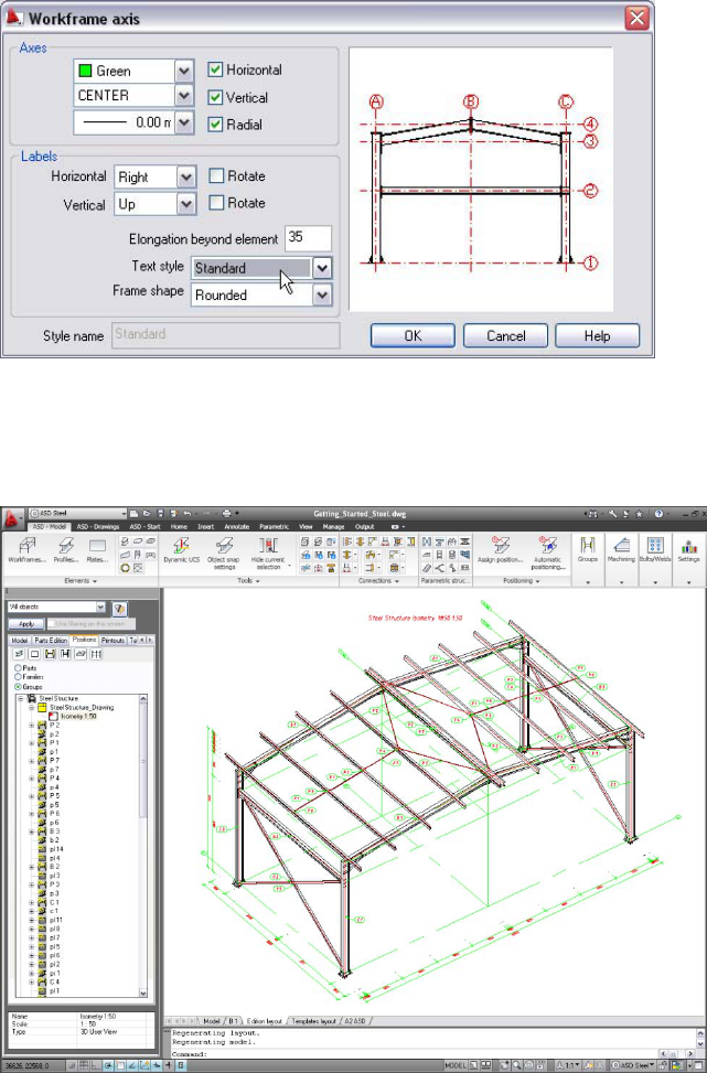
AtthebottomrightoftheDimensioningstylesettings–Group
dialog,click(nexttoWorkframeaxes).
IntheWorkframeaxisdialog,forTextstyle,selectStandard,and
thenclickOK.
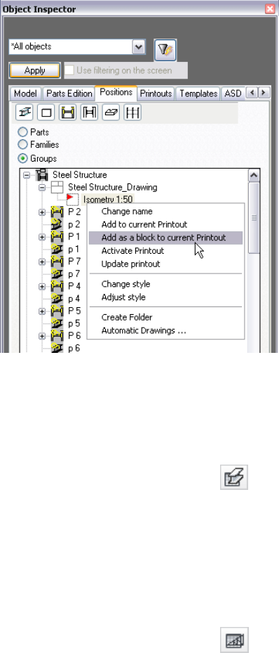
43
Themodifiedview(withoutinvisibleedgesofprofilesandwith
changeddescriptionstylesofAssembliesandWorkframeAxes)
displaysasshown.
5 Addnewprintout:
OntheLayout/ModelTabBar,clickanytab,right‐click,andclick
Fromtemplate.
IntheSelecttemplatefromfiledialog,selectA2ASD033.dwt,and
clickOpen.
ClickOKtoacceptA2ASDasthelayoutname.
44
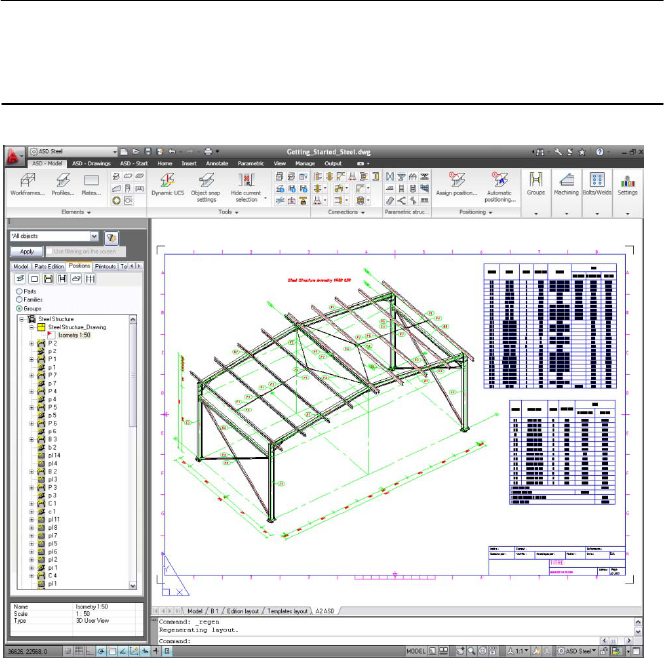
6 ManuallyaddaSteelStructureisometricviewtothegeneral
arrangementsdrawing:
OntheLayout/ModelTabBar,clicktheA2ASDtab.
OnthePositionstaboftheObjectInspector,selectIsometry1:50,
right‐click,andclickAddasblocktocurrentprintout.
Inthedrawingarea,clicktospecifyaninsertionpointfortheblock.
7 Manuallyadddifferenttypesoftablestothegeneralarrangements
drawing:
ClickASD‐Drawings
hTablesh (Billofmaterials).
Alternatively,clickSteelmenuhReportshBillofmaterials.
PressEntertoacceptthetablerangeasalistfortheentire
structure.
Inthedrawingarea,clicktospecifyaninsertionpointfortheblock.
ClickASD‐Drawings
hTablesh (Listofassemblies).
Alternatively,clickSteelmenuhReportshListofassemblies.
PressEntertoacceptthetablerangeasalistfortheentire
structure.
45
46
Inthedrawingarea,clicktospecifyaninsertionpointfortheblock.
NOTEToadjustthesizeoftablestothedrawingformat,clickontable,
right‐click,andclickModify.Changethewidth/heightofcolumnsandrows
bydraggingthemtotherequiredsize.
YouhavecompletedtheAutoCAD®StructuralDetailing2011Steel
ModuleGettingStartedGuide.
