
CHARLOTTE FIRE DEPARTMENT
FIRE MARSHAL’SOFFICE
500 DALTON AVE
CHARLOTTE, NC 28206
Charlotte Fire Department | 500 Dalton Avenue | Charlotte, NC 28206
Rev 10/25/2023
Fire Plan Review Guidelines
General Requirements
A. Submittal Requirements:
1. Building permit information can be found on Mecklenburg County’s “LUESA” site. Click Here
2. City of Charlotte Planning Department (City Engineering). Click Here
B. Appendix B:
1. Provide information for the entire project and include the following:
a. Project name and address
b. Fire district status
c. Occupant load
d. Seismic category
e. Fire alarm status and type
f. Sprinkler status and type
New/Shell Building Requirements
A. Site Requirements:
1. Fire apparatus access roads shall have an unobstructed width of not less than 20 feet and an
unobstructed vertical clearance of not less than 14 feet. This shall include multi-family properties
and residential communities with privately maintained streets; on-street parking shall be
prohibited unless the minimum 20 feet width can be established and maintained.

CHARLOTTE FIRE DEPARTMENT
FIRE MARSHAL’SOFFICE
500 DALTON AVE
CHARLOTTE, NC 28206
Charlotte Fire Department | 500 Dalton Avenue | Charlotte, NC 28206
Rev 10/25/2023
2. Dead-end fire apparatus access roads in excess of 150 feet in length shall be provided with an
approved area for turning around fire apparatus.
3. The minimum turning radius shall be 42 feet-3 1/2 inch outside and 30 feet inside for all
proposed fire apparatus access roads.
4. Fire apparatus access roads shall not have a slope greater than 10%.
5. Fire apparatus access roads shall be designed and maintained to support the imposed loads of fire
apparatus and shall be surfaced to provide all-weather driving capabilities. CFD’s largest trucks
(ladder companies) have a Gross Vehicle Weight (GVW) of 85,000 lbs.
6. Fire apparatus access roads shall be within 200 feet of all exterior walls of sprinkled buildings and
150 feet of all exterior walls of non-sprinkled buildings.
B. Water Supply:
1. Current hydrant test shall be included in shell submittals for all buildings that have an ISO NFF
calculation or has a wet standpipe that is served by a fire pump.
2. An ISO needed fire flow (NFF) calculation shall be completed for all non-sprinkled buildings,
NFPA 13D and NFPA 13R Systems.
3. For non-sprinkled buildings - An approved fire hydrant shall be located within 400 feet from the
most remote point of all buildings and measured “as an approved apparatus route as determined
by the fire code official”. (NCIFC 2018 ed. Sec. 507.5.1.)
4. For sprinkled buildings - An approved fire hydrant shall be located within 600 feet from the most
remote point of all buildings and measured “as an approved apparatus route as determined by the
fire code official”. (NCIFC 2018 ed. Sec. 507.5.1. exception #2)
5. Fire department connections (FDCs) that serve standpipe systems shall be within 100 feet of a
fire hydrant (NCIFC 2018 ed. Section 507.5.1.1.)
6. The fire department connection (FDC) shall not be greater than 50 feet from a fire department
access road.
7. Water mains that are 6 inches in diameter and serving a fire hydrant shall not exceed 350 feet in
length.

CHARLOTTE FIRE DEPARTMENT
FIRE MARSHAL’SOFFICE
500 DALTON AVE
CHARLOTTE, NC 28206
Charlotte Fire Department | 500 Dalton Avenue | Charlotte, NC 28206
Rev 10/25/2023
8. Show an NFPA 13 FDC location within 200 feet of a fire hydrant as the truck travels. (See water
supply Section.)
9. Show an NFPA 13R FDC location within 200 feet of a fire hydrant as the truck travels. (See
water supply Section.)
10. Show all existing and new hydrant locations, including size of mains. Friction loss
calculations shall be required for all new hydrant installations in a water-model format.
11. Buildings protected with an NFPA 13R sprinkler system shall be calculated, with a 50% credit
allowance given on the NFF.
12. Include recent hydrant flow test (within the past 12 months) of the most remote hydrant at 20
psi from our hydrant test coordinator by calling 704-336-2101 or Click Here.
13. For all buildings being served by a fire pump the following must be provided. Pump information
including but not limited to, pump driver details including manufacturer, horsepower, voltage, or
fuel system details, rated capacity and location of pump.
C. Fire Sprinkler Protection: *
1. As of 1 January 2023, an Owner’s Certificate will be required for sprinkler shop drawings (NFPA 13
Section 23.1.4)
2. Provide the sprinkler design criteria based off the 48-hr. low hydrant test. A hydraulic adjustment
is required to adjust the water supply curve to the lowest pressures the system encounters during a
48-hour time period. Adjustment of the water supply curve entails shifting both the static and
residual pressures downward to the lowest static pressure the system encountered during the 48-
hour test. The curve should show two curves in parallel shifted along the y-axis. See example:
Water supply calculation example:
48-hour low: 70 psi static
Conditions during flow test: 80 psi static 65 psi residual 965 gpm.
Adjustment: 70 psi static 55 psi residual 965 gpm.
3. Show all FDC and hydrant locations.

CHARLOTTE FIRE DEPARTMENT
FIRE MARSHAL’SOFFICE
500 DALTON AVE
CHARLOTTE, NC 28206
Charlotte Fire Department | 500 Dalton Avenue | Charlotte, NC 28206
Rev 10/25/2023
4. Provide riser diagram and type of system.
5. Show the riser location.
6. Provide vertical elevation of each floor
*Fire sprinkler shop drawings are required for all new systems.
D. Fire Alarm Systems: *
1. Show all notification and initiating devices, note new-N, existing-E including candela ratings and
the (FACP) location.
2. Provide the riser diagram including all devices and monitoring of all suppression systems.
3. Provide the matrix/sequence of operations.
*Fire alarm shop drawings are required for all new systems.
4. Design Professional shall provide information as required in NCIFC 2018 ed. Sec. 907.1 - 907.1.2
to include 1 through 8 and 12 through 14, since NC Admin. Code does not recognize a NICET
Fire Alarm Technician as a design professional.
E. Standpipe Systems:
1. Provide the type of system and note “wet” or “dry”.
2. FDC location shall be within 100 feet of an approved hydrant and with-in 50 feet of access road.
3. Hose valves shall be on all floor landings, NOT intermediate landings. Additional hose valves are
required where the most remote portion of a floor or area exceeds 200 feet from a hose connection
for a sprinkled building, or 150 feet for a non-sprinkled building.
4. Provide vertical standpipe riser diagram to include stair elevation diagram (isometric view).
5. (1) 2 1/2” inlet will be provided per 250 gpm. of required standpipe demand.
*Design per NFPA 14
CHARLOTTE FIRE DEPARTMENT
FIRE MARSHAL’SOFFICE
500 DALTON AVE
CHARLOTTE, NC 28206
Charlotte Fire Department | 500 Dalton Avenue | Charlotte, NC 28206
Rev 10/25/2022
6. Hydraulic Design for Manual Standpipes:
F. Alternative Suppression Systems:
1. Engineer to provide the design criteria and type of system being used.
2. Provide detail of the fire suppression system being installed. The details shall include size, length,
and arrangement of connected piping. Description and location of nozzles.
3. Provide information pertaining to the location and function of detection devices, operating
devices, auxiliary equipment, and electrical circuitry.
4. Provide cut sheets of new equipment.
*Shop Drawings are not required for alternative suppression systems.
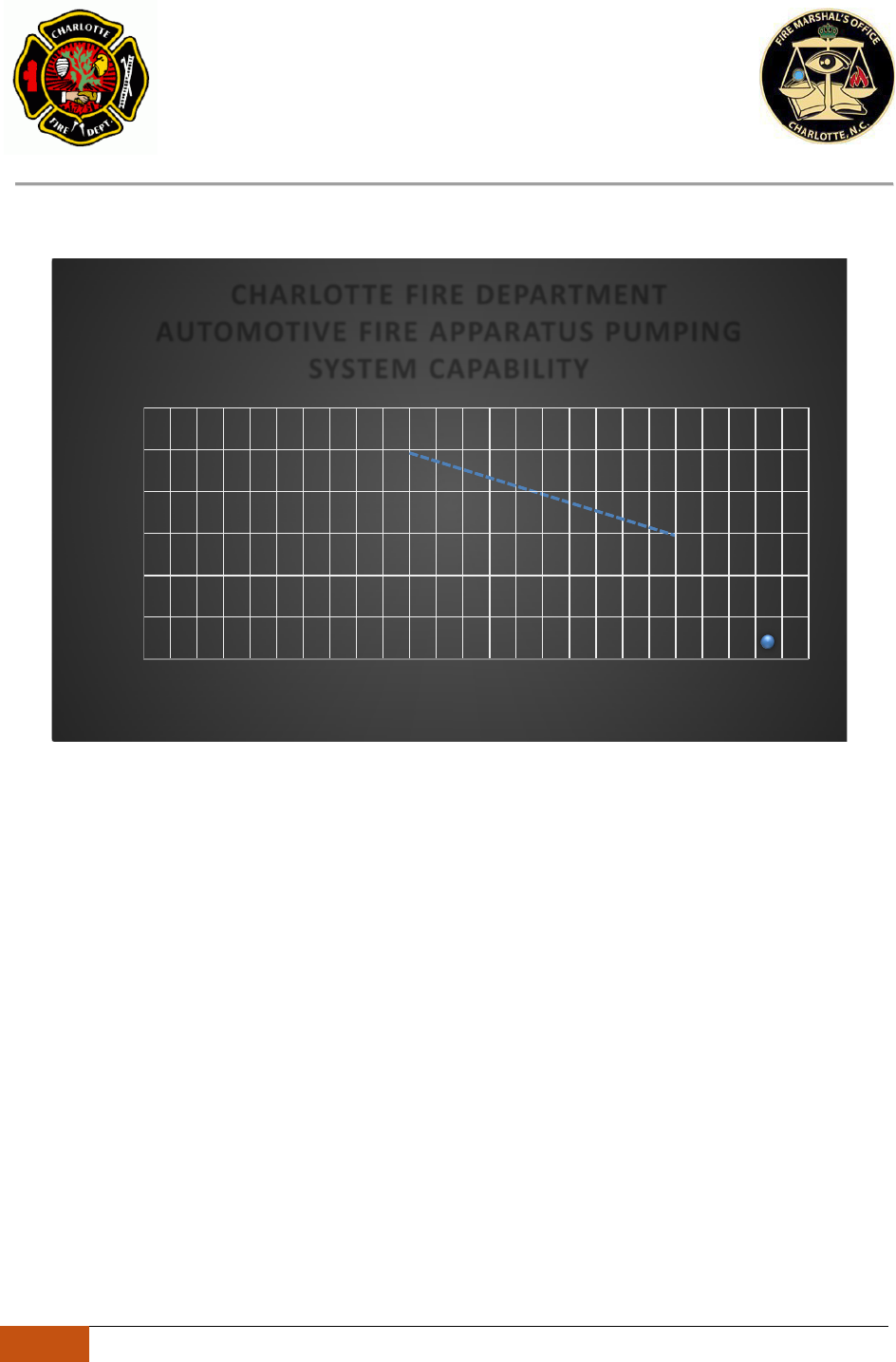
CHARLOTTE FIRE DEPARTMENT
AUTOMOTIVE FIRE APPARATUS PUMPING
SYSTEM CAPABILITY
300
250
200
% RATED
C
APACIT
150
70% R
ATE
C
APACIT
100 %
100
C
APA
IT
50
0
0 500 1000
1500
2000
2500
FLOW IN GPM
Y
ED
RAT
Y
D
Y
50
NET PRESSURE IN PSI

CHARLOTTE FIRE DEPARTMENT
FIRE MARSHAL’SOFFICE
500 DALTON AVE
CHARLOTTE, NC 28206
Charlotte Fire Department | 500 Dalton Avenue | Charlotte, NC 28206
Rev 10/25/2022
G. Emergency Responder Radio Coverage (ERRC)
1. All new buildings shall have approved radio coverage for emergency responders within the
building based upon the existing coverage levels of the public safety communication systems of
the jurisdiction at the exterior of the building. NCIFC 2018 ed. Sec. 510.1, 510.4.1.
2. The in-building 2- way emergency responder communication coverage system shall be designed
in accordance with Sections 510.4.2.1 through 510.4.2.8 and NFPA 1221.
3. Amplification systems and components. Buildings and structures that cannot support the required
level of in-building 2- way emergency responder communication coverage shall be equipped with
systems and components to enhance the radio signals and achieve the required level of emergency
communication coverage specified in Sections 510.4.1 through 510.4.1.3. Emergency
communication systems utilizing radio-frequency-emitting devices and cabling shall be approved
by the fire code official. Prior to installation, all RF-emitting devices shall have the certification
of the radio licensing authority and be suitable for public safety use.
4. Technical criteria. The fire code official shall maintain a document providing the specific
technical information and requirements for the in-building 2- way emergency responder
communication coverage system. This document shall contain, but not be limited to, the various
frequencies required, the location of radio sites, the effective radiated power of radio sites, the
maximum propagation delay in microseconds, the applications being used and other supporting
technical information necessary for system design.
5. Standby power. In-building 2- way emergency responder communication coverage systems shall
be provided dedicated standby power or provided with 2-hour standby batteries and connected
to the facility generator power system in accordance with Section 604. The standby power
supply shall be capable of operating the in-building 2- way emergency responder
communication coverage system. at 100-percent system capacity for a duration of not less
than 12 hours.
6. Signal booster requirements. If used, signal boosters shall meet the following requirements:
a. All signal booster components shall be contained in a National Electrical Manufacturer’s
Association (NEMA) 4-type waterproof cabinet.

CHARLOTTE FIRE DEPARTMENT
FIRE MARSHAL’SOFFICE
500 DALTON AVE
CHARLOTTE, NC 28206
Charlotte Fire Department | 500 Dalton Avenue | Charlotte, NC 28206
Rev 10/25/2023
b. Battery systems used for the emergency power source shall be contained in a 3R or
higher- rated cabinet.
c. Equipment shall have FCC or other radio licensing authority certification and be suitable for
public safety use prior to installation.
d. Where a donor antenna exists, isolation shall be maintained between the donor antenna and all
inside antennas to not less than 20dB greater than the system gain under all operating
conditions.
e. Active RF emitting devices used in in-building 2- way emergency responder communication
coverage systems shall have built-in oscillation detection and control circuitry.
7. The installation of amplification systems or systems that operate on or provide the means to cause
interference on any in-building 2- way emergency responder communication coverage network
shall be coordinated and approved by the fire code official.
8. System monitoring. The in-building 2-way emergency responder communication coverage system
shall be monitored by a listed fire alarm control unit, or when approved by the fire code official,
shall sound an audible signal at a constantly attended on-site location. Automatic supervisory
signal shall include the following:
a. Loss of normal AC power supply.
b. System battery charger(s) failure.
c. Malfunction of the donor antenna(s).
d. Failure of active RF-emitting device(s).
e. Low-battery capacity at 70-percent reduction of operating capacity.
f. Failure of critical system components.
g. The communications link between the fire alarm system and the in-building 2- way
emergency responder communication coverage system.
h. Oscillation of active RF-emitting device(s)
9. Additional frequencies and change of frequencies. The in-building 2- way emergency
responder communication coverage system shall be capable of modification or expansion in
the event frequency changes are required by the FCC or other radio licensing authority, or
additional frequencies are made available by the FCC or other radio licensing authority.

CHARLOTTE FIRE DEPARTMENT
FIRE MARSHAL’SOFFICE
500 DALTON AVE
CHARLOTTE, NC 28206
Charlotte Fire Department | 500 Dalton Avenue | Charlotte, NC 28206
Rev 10/25/2023
10. Design documents. The fire code official shall have the authority to require “as-built” design
documents and specifications for in-building 2- way emergency responder communication
coverage systems. The documents shall be in a format acceptable to the fire code official.
11. Radio communication antenna density. Systems shall be engineered to minimize the near-far
effect. In-building 2-way emergency responder communication coverage system designs shall
include sufficient antenna density to address reduced gain conditions.
Upfit/Existing Buildings
A. Fire Sprinkler Protection
1. Show all sprinkler head locations on a reflected ceiling plan (RCP) or fire protection sheet (FP).
2. Identify all sprinkler heads as new, existing, relocated, or plugged.
3. Show all ceiling obstructions and walls and show heads on both sides of new tenant
separation walls.
*Fire Sprinkler Shop Drawings are required when adding 20 or more heads. Can be deferred
within 90 days of issuance of permit.
B. Fire Alarm Systems:
1. Indicate all notification and initiating devices, show new-N, show existing-E including
candela ratings and the FACP location.
2. Provide the riser diagram including all devices and monitoring of all suppression systems.
3. Provide the matrix/sequence of operations.
4. Design Professional shall provide information as required in NCIFC 2018 ed. Sec. 907.1 - 907.1.2
to include 1 through 7 and 12 through 14, since NC Admin. Code does not recognize a NICET
Fire Alarm Technician as a design professional.
*Fire Alarm Shop Drawings are required for 5 or more devices and new panels. Multi-tenant
buildings may require shop drawings per the field inspector. The Fire Alarm contractor is
responsible for calculations to verify adequate power for addition of new devices.

CHARLOTTE FIRE DEPARTMENT
FIRE MARSHAL’SOFFICE
500 DALTON AVE
CHARLOTTE, NC 28206
Charlotte Fire Department | 500 Dalton Avenue | Charlotte, NC 28206
Rev 10/25/2023
C. Alternative Suppression Systems:
1. Engineer shall provide the design criteria and type of system being used.
2. Provide cut sheets of new equipment.
*Shop Drawings are not required for alternative suppression systems, but such systems must be
installed per manufacturer’s specifications. All pre-engineered systems shall be shown on the
permit plans.
Special Circumstances/Use
A. High-rise Buildings:
1. For two-way fire department communications, although the North Carolina Fire Code requires
that a two-way fire department communication system comply with NFPA 72 be installed in
high-rise buildings, with a repeater system being the “exception”, the Charlotte Fire
Department
requires a repeater system. If a designer/building owner wishes to install fire phones complying
with NFPA 72, that will be an added level of protection, but not an alternative.
2. Pressure reducing valves (PRV) are required to be field adjustable.
3. For buildings, structures, or parts thereof required by the International Building Code or the
NCIFC to have a smoke control system or systems shall have such systems designed in
accordance with the applicable requirements of NCIFC 2018 ed Section 909 and the generally
accepted and well-established principles of engineering relevant to the design. The construction
documents shall include sufficient information and detail to describe adequately the elements of
the design necessary for the proper implementation of the smoke control systems. These
documents shall be accompanied with sufficient information and analysis to demonstrate
compliance with these provisions.

CHARLOTTE FIRE DEPARTMENT
FIRE MARSHAL’SOFFICE
500 DALTON AVE
CHARLOTTE, NC 28206
Charlotte Fire Department | 500 Dalton Avenue | Charlotte, NC 28206
Rev 10/25/2023
4. In addition to the ordinary inspection and test requirements that buildings, structures and parts
thereof are required to undergo, smoke control systems subject to the provisions of NCIFC 2018
ed. Section 909 shall undergo special inspections and tests sufficient to verify the proper
commissioning of the smoke control design in its final installed condition. The design submission
accompanying the construction documents shall clearly detail procedures and methods to be
used and the items subject to such inspections and tests. Such commissioning shall be in
accordance with generally accepted engineering practice and, where possible, based on
published standards for the testing involved. The special inspections and tests required by the
NCIFC shall be conducted under the same terms as in Section 1704 of the International
Building Code.
5. A rational analysis performed by the registered design professional and approved by the fire code
official supporting the types of smoke control systems to be employed, the methods of their
operations, the systems supporting them and the methods of construction to be utilized shall
accompany the construction documents submission and include, but not be limited to, the items
indicated in Sections 909.4.1 through 909.4.7. of the NCIFC.
6. Smoke barriers required for passive smoke control and a smoke control system using the
pressurization method shall comply with Section 709 of the International Building Code. The
maximum allowable leakage area shall be the aggregate area calculated using the following
leakage area ratios:
a) Walls: A/Aw = 0.00100
b) Interior exit stairways and ramps and exit passageways: A/Aw = 0.00035
c) Enclosed exit access stairways and ramps and all other shafts: A/Aw = 0.00150

CHARLOTTE FIRE DEPARTMENT
FIRE MARSHAL’SOFFICE
500 DALTON AVE
CHARLOTTE, NC 28206
Charlotte Fire Department | 500 Dalton Avenue | Charlotte, NC 28206
Rev 10/25/2023
d) Floors and roofs: A/AF = 0.00050 where: A = Total leakage area, square feet (m2).
AF = Unit floor or roof area of barrier, square feet (m2).
Aw = Unit wall area of barrier, square feet (m2).
The leakage area ratios shown do not include openings due to gaps around doors and operable
windows. The total leakage area of the smoke barrier shall be determined in accordance with
Section 909.5.1 and tested in accordance with Section 909.5.2.
7. The primary mechanical means of controlling smoke shall be by pressure differences across
smoke barriers. Maintenance of a tenable environment is not required in the smoke-control zone
of fire origin.
8. Where approved by the fire code official, smoke migration through openings fixed in a
permanently open position, which are located between smoke control zones using the airflow
method, shall be permitted. The design airflow shall be in accordance with this section. Airflow
shall be directed to limit smoke migration from the fire zone. The geometry of openings shall be
considered to prevent flow reversal from turbulent effects. Smoke control systems using the
airflow method shall be designed in accordance with NFPA 92.
9. Where approved by the fire code official, mechanical smoke control for large, enclosed volumes,
such as in atriums or malls, shall be permitted to utilize the exhaust method. Smoke control
systems using the exhaust method shall be designed in accordance with NFPA 92.
10. The design fire shall be based on a rational analysis performed by the registered design
professional and approved by the fire code official. The design fire shall be based on the analysis
in accordance with Section 909.4 through 909.9.4, where applicable.
11. Equipment including, but not limited to, fans, ducts, automatic dampers, and balance dampers
shall be suitable for their intended use, suitable for the probable exposure temperatures that the
rational analysis indicates, and as approved by the fire code official. Refer to NCIFC Sections
909.10.1 through 909.10.5.
12. Smoke control systems shall be provided with standby power in accordance with NCIFC Section
604.
13. Fire detection systems providing control input or output signals to mechanical smoke control
systems or elements thereof shall comply with the requirements of Section 907 and Sections

CHARLOTTE FIRE DEPARTMENT
FIRE MARSHAL’SOFFICE
500 DALTON AVE
CHARLOTTE, NC 28206
Charlotte Fire Department | 500 Dalton Avenue | Charlotte, NC 28206
Rev 10/25/2023
909.12 through 909.12.4. Such systems shall be equipped with a control unit complying with UL
864 and listed as smoke control equipment.
14. Control air tubing shall be of sufficient size to meet the required response times. Tubing shall be
flushed clean and dry prior to final connections and shall be adequately supported and protected
from damage. Tubing passing through concrete or masonry shall be sleeved and protected from
abrasion and electrolytic action as listed in NCIFC 909.13.1 through 909.13.3.
15. Identical control diagrams showing all devices in the system and identifying their location
and function shall be maintained current and kept on file with the fire code official, the fire
department and in the fire command center in a format and manner approved by the fire chief.
16. A fire fighter’s smoke control panel for fire department emergency response purposes only
shall be provided and shall include manual control or override of automatic control for
mechanical smoke control systems. The panel shall be in a fire command center complying
with NCIFC Section 508 in high-rise buildings or buildings with smoke-protected assembly
seating. In all other buildings, the fire fighter’s smoke control panel shall be installed in an
approved location adjacent to the fire alarm control panel. The fire fighter’s smoke control
panel shall comply with Sections 909.16.1 through 909.16.3.
17. Smoke-control system activation shall be initiated immediately after receipt of an appropriate
automatic or manual activation command. Smoke control systems shall activate individual
components (such as dampers and fans) in the sequence necessary to prevent physical damage to
the fans, dampers, ducts, and other equipment. For purposes of smoke control, the fire fighter’s
control panel response time shall be the same for automatic or manual smoke control action
initiated from any other building control point. The total response time, including that necessary
for detection, shutdown of operating equipment and smoke control system startup, shall allow
for full operational mode to be achieved before the conditions in the space exceed the design
smoke condition. The system response time for each component and their sequential
relationships shall be detailed in the required rational analysis and verification of their installed
condition reported in the required final report.

CHARLOTTE FIRE DEPARTMENT
FIRE MARSHAL’SOFFICE
500 DALTON AVE
CHARLOTTE, NC 28206
Charlotte Fire Department | 500 Dalton Avenue | Charlotte, NC 28206
Rev 10/25/2023
18. Five floor grouping for fire alarm notification is the acceptable means for high-rise buildings.
The fire alarm shall be zoned/grouped for five floors which are: the fire floor, two above it, and
two below it. This is a CFD FMO Operating Guideline approved by the Fire Marshal.
19. Five floor grouping for fire evacuation is the acceptable means for high-rise buildings. The fire
alarm shall be zoned/grouped for five floors which are (commonly referred to as the “Rule of 5”
or “5 Move 5”): the fire floor, two above it for safety, and two below it (so that the second floor
below the fire floor can be used as a staging area for fire department operations). Occupants on
these five floors are relocated down five floors thus being relocated to at least three floors from
the fire floor; if the fire is on or below a floor that is six floors from street level, the occupants
usually will be evacuated from the building. The evacuation plan must be submitted to the
Inspector for approval. This is a CFD FMO Operating Guideline approved by the Fire Marshal.
B. Cell Phone Towers:
1. Site shall be provided with an approved fire department access road of not less than 20 feet
in width, and an unobstructed vertical clearance of not less than 14 feet.
2. Dead-end fire apparatus access roads in excess of 150 feet in length shall be provided with an
approved area for turning around fire apparatus.
3. The minimum turning radius shall be 42 feet-3 1/2 inches outside and 30 feet inside for the
proposed fire apparatus access road.
4. Fire apparatus access road shall not have a slope greater than 10%.
5. Fire apparatus access road shall be designed and maintained to support the imposed loads of fire
apparatus and shall be surfaced so as to provide all-weather driving capabilities. CFD’s largest
trucks (ladder companies) have a Gross Vehicle Weight (GVW) of 85,000 lbs.
6. Fire apparatus access road shall be within 150 feet of all exterior walls of the building (200 feet if
building is sprinkled).

CHARLOTTE FIRE DEPARTMENT
FIRE MARSHAL’SOFFICE
500 DALTON AVE
CHARLOTTE, NC 28206
Charlotte Fire Department | 500 Dalton Avenue | Charlotte, NC 28206
Rev 10/25/2023
C. Gates and Access Controlled Fencing:
1. Must be a minimum width of 20 feet for undivided entry/exit or 16 feet for divided entry/exit.
2. All gates shall have a Knox Box or Knox Switch for fire department access.
3. Electric gate operators, where provided, shall be listed in accordance with UL 325. Gates
intended for automatic operation shall be designed, constructed, and installed to comply with
the requirements of ASTM F2200.
Shop Drawing Requirements
A. Plan Submittal:
1. Fire alarm systems:
Shop drawing submittal for fire alarm systems shall include, but not be limited to, the following
information, in accordance with Section 907 of the North Carolina Fire Code and NFPA 72
Section 7.4 under the current recognized standard edition or the latest edition but must be usedin
its entirety:
• A floor plan that indicates the use of all rooms.
• Locations of alarm-initiating devices.
• Locations of alarm notification appliances, including candela ratings for
visible appliances.
• Location of fire alarm control unit, transponders and notification power
supplies.
• Annunciators.
• Power connection.
• Battery calculations.
• Conductor type and sizes.
• voltage drop calculations.
• Manufacture’s cut sheets for equipment, devices and materials.
• Details of ceiling heights and construction.

CHARLOTTE FIRE DEPARTMENT
FIRE MARSHAL’SOFFICE
500 DALTON AVE
CHARLOTTE, NC 28206
Charlotte Fire Department | 500 Dalton Avenue | Charlotte, NC 28206
Rev 10/25/2023
• The interface of fire safety control functions.
• Classification of supervising station.
2. Fire sprinkler systems:
Shop drawing submittal for fire protection systems shall include, but not be limited to, the
following information, in accordance with Section 907 of the North Carolina Fire Code and
NFPA 13 Chapter 23 under the current recognized standard edition or the latest edition but must
be used in its entirety:
• Cut sheets for sprinkler heads.
• Hydraulic calculations (must include all fixed losses per manufacturers cut
sheets to include metering devices tapped to a City main and a fixed loss
of 15psi for all backflow preventers).
• Utility plans indicating all below-ground piping and associated connections
including sectional valves, PIVs and control valves.
• Owner’s Certificate.
• Fire hydrant flow test or existing fire pump test within a 12-month period.
• Provide a permanent means to test the backflow downstream.
B. Submittal Timeline:
1. Shop drawings shall be submitted within 90 days of building permit issuance. Installation shall
not take place until plans are reviewed and approved.
2. Plans will be reviewed within 15 business days, based on the size of the project from the
date the reviewer receives them. If you are submitting midrise and high-rise shell projects,
Group H, and Group I based upon the size of the project your turn around time will not be
more than 30 days. We will notify the submitter when the review has been completed.

CHARLOTTE FIRE DEPARTMENT
FIRE MARSHAL’SOFFICE
500 DALTON AVE
CHARLOTTE, NC 28206
Charlotte Fire Department | 500 Dalton Avenue | Charlotte, NC 28206
Rev 10/25/2023
C. Submittal Procedure: *
As of January 1, 2023, Charlotte Fire Department required shop drawings for projects in the
Charlotte city limits be submitted through this Electronic Plan Management (EPM) portal. The
first web link is to help you with setting up an account and submitting through EPM. The
second web link is how to submit an RTAP. Most shop drawings are to be submitted as an
RTAP. The only time it will be a standalone project is when there is no project in which to
attach the shop drawing.
1) https://www.mecknc.gov/LUESA/CodeEnforcement/Documents/EPM01-
CreatinganAccount-ManagingUsers.pdf
2) https://www.mecknc.gov/LUESA/CodeEnforcement/Documents/EPM15-
RTAPReviewProcess-PackagingSubmittal.pdf
Any resubmittal of plans that were originally submitted through the email portal shall be
submitted back through the e-mail portal until approved.
[email protected]lotte.nc.us
By using the six-digit project number assigned by the county at time of the original permit
application by the architect, the system should recognize the project as a city fire or county fire
assignment. Contact either: Cherly.Dean@mecklenburgcountync.gov
or
[email protected] at the county for additional information. For city fire
questions on the submittal contact Jeffory.[email protected]. The process will be
similar to the process used by the Mecklenburg County Fire Marshal’s office.
Contact Ryan Woods at [email protected]v to set up a city account. CFD is no
longer collecting shop drawing review fees via credit card or online payment using the new
submittal system. Submitting company MUST have a city account effective March 1, 2023

CHARLOTTE FIRE DEPARTMENT
FIRE MARSHAL’SOFFICE
500 DALTON AVE
CHARLOTTE, NC 28206
Charlotte Fire Department | 500 Dalton Avenue | Charlotte, NC 28206
Rev 10/25/2023
D. Review Application and Fees:
*Fees are assessed on every submittal whether the plans are approved or disapproved.
Hydrant Test - 34a - $135.00
Rezoning Petitions – Major - 34b - $140.00
Rezoning Petitions – Minor - 34t - $45.00 Multi Family - 34c - $235.00
Fire Alarm Plans (Shop drawings) - 34d - $135.00
Fire Sprinkler Plans (Shop drawings) - 34e - $215.00
Plans Review- Const. less than 50,000 - 34g - $105.00
Plans Review-Const. $50,001 to 100,000 - 34h - $135.00
Plans Review-Const. $100,001 to 500,000 - 34i - $190.00
Plans Review-Const. $500,001 to 1,000,000 - 34j - $215.00
Plans Review-Const. $1,000,001 to 5,000,000 - 34k - $245.00
Plans Review-Const. $5,000,001 to 10,000,000 - 34l - $380.00
Plans Review-Const. Greater Than 10,000,000 - 34m - $1,090.00
Performance Tests - Fire pumps - 34n - $160.00
Performance Tests - Sprinkler System - 34o - $215.00
Performance Tests - Fire Alarm (Shell) - 34p - $215.00
Performance Tests - Fire Alarm (Upfit) - 34q - $215.00
Performance Tests - Private fire hydrants - 34r - $90.00
Performance Tests - Standpipe system tests - 34s - $215.00
Performance Tests - Automatic fire-extinguishing systems - 34f - $80.00
Kevin Miller, Fire Marshal
Charlotte Fire Department
Fire Prevention
Fire Marshal’s Office
