114 690 01 Rev. G KohlerEngines.com
XT-6, XTR-6, XT6.5, XT650, XT6.75, XT675,
XT-7, XTR-7, XT775, XT8
Service Manual
2 Safety
3 Maintenance
5 Specications
10 Tools and Aids
13 Troubleshooting
17 Air Cleaner/Intake
18 Fuel System
24 Governor System
26 Lubrication System
27 Electrical System
31 Starter System
33 Disassembly/Inspection and Service
45 Reassembly
IMPORTANT: Read all safety precautions and instructions carefully before operating equipment. Refer to operating
instruction of equipment that this engine powers.
Ensure engine is stopped and level before performing any maintenance or service.
2
Safety
KohlerEngines.com 14 690 01 Rev. G
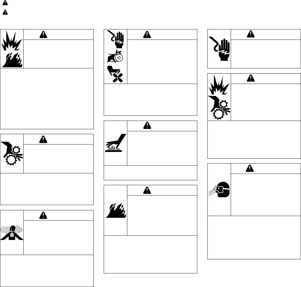
SAFETY PRECAUTIONS
WARNING: A hazard that could result in death, serious injury, or substantial property damage.
CAUTION: A hazard that could result in minor personal injury or property damage.
NOTE: is used to notify people of important installation, operation, or maintenance information.
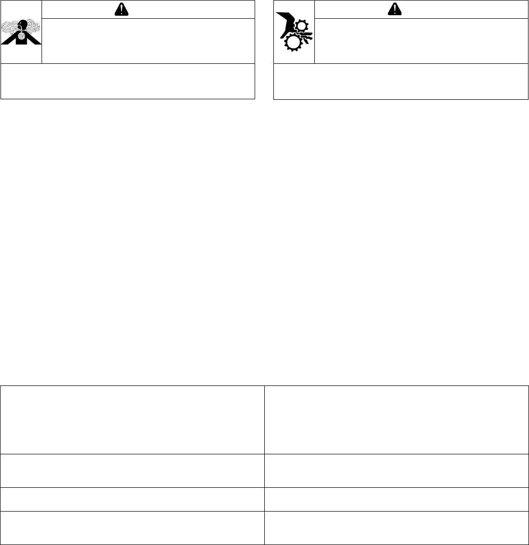
WARNING
Explosive Fuel can cause
res and severe burns.
Do not ll fuel tank while
engine is hot or running.
Gasoline is extremely ammable
and its vapors can explode if
ignited. Store gasoline only in
approved containers, in well
ventilated, unoccupied buildings,
away from sparks or ames.
Spilled fuel could ignite if it comes
in contact with hot parts or sparks
from ignition. Never use gasoline
as a cleaning agent.
WARNING
Rotating Parts can cause
severe injury.
Stay away while engine
is in operation.
Keep hands, feet, hair, and
clothing away from all moving
parts to prevent injury. Never
operate engine with covers,
shrouds, or guards removed.
WARNING
Carbon Monoxide can
cause severe nausea,
fainting or death.
Avoid inhaling exhaust
fumes.
Engine exhaust gases contain
poisonous carbon monoxide.
Carbon monoxide is odorless,
colorless, and can cause death if
inhaled.
WARNING
Accidental Starts can
cause severe injury or
death.
Disconnect and ground
spark plug lead(s) before
servicing.
Before working on engine or
equipment, disable engine as
follows: 1) Disconnect spark plug
lead(s). 2) Disconnect negative (–)
battery cable from battery.
WARNING
Hot Parts can cause
severe burns.
Do not touch engine
while operating or just
after stopping.
Never operate engine with heat
shields or guards removed.
WARNING
Cleaning Solvents can
cause severe injury or
death.
Use only in well
ventilated areas away
from ignition sources.
Carburetor cleaners and solvents
are extremely ammable. Follow
cleaner manufacturer’s warnings
and instructions on its proper and
safe use. Never use gasoline as a
cleaning agent.
CAUTION
Electrical Shock can
cause injury.
Do not touch wires while
engine is running.
CAUTION
Damaging Crankshaft
and Flywheel can cause
personal injury.
Using improper procedures can
lead to broken fragments. Broken
fragments could be thrown from
engine. Always observe and use
precautions and procedures when
installing ywheel.
WARNING
Uncoiling Spring can
cause severe injury.
Wear safety goggles or
face protection when
servicing retractable
starter.
Retractable starters contain a
powerful, recoil spring that is
under tension. Always wear safety
goggles when servicing retractable
starters and carefully follow
instructions in Retractable Starter
for relieving spring tension.
3
Maintenance
14 690 01 Rev. G KohlerEngines.com
MAINTENANCE INSTRUCTIONS
WARNING
Before working on engine or equipment, disable engine as
follows: 1) Disconnect spark plug lead(s). 2) Disconnect
negative (–) battery cable from battery.
Accidental Starts can cause severe injury or
death.
Disconnect and ground spark plug lead(s)
before servicing.
Normal maintenance, replacement or repair of emission control devices and systems may be performed by any repair
establishment or individual; however, warranty repairs must be performed by a Kohler authorized dealer.
MAINTENANCE SCHEDULE
After rst 3-5 Hours
● Change oil. Lubrication System
Every 25 Hours or Annually¹
● Service/replace precleaner. Air Cleaner/Intake
● Check air cleaner for dirty, loose or damaged parts. Air Cleaner/Intake
Every 50 Hours or Annually
● Change oil. Lubrication System
● Replace fuel lter (if equipped).
Every 50 Hours or Annually¹
● Replace air cleaner element. Air Cleaner/Intake
Every 100 Hours or Annually¹
● Clean spark arrestor (if equipped).
Every 100 Hours or Annually²
● Have combustion chamber decarbonized.
Every 125 Hours or Annually¹
● Replace spark plug and set gap. Electrical System
1
Perform these procedures more frequently under severe, dusty, dirty conditions.
2
Have a Kohler authorized dealer perform this service.
REPAIRS/SERVICE PARTS
Kohler genuine service parts can be purchased from Kohler authorized dealers. To nd a local Kohler authorized
dealer visit KohlerEngines.com or call 1-800-544-2444 (U.S. and Canada).
4
Maintenance
KohlerEngines.com 14 690 01 Rev. G
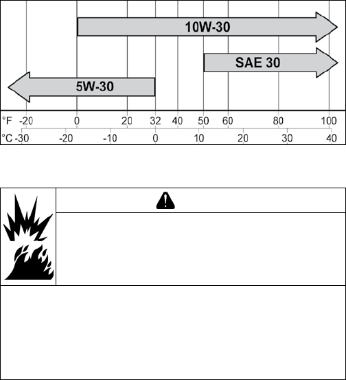
OIL RECOMMENDATIONS
We recommend use of Kohler oils for best performance.
Other high-quality detergent oils (including synthetic)
of API (American Petroleum Institute) service class SJ
or higher are acceptable. Select viscosity based on
air temperature at time of operation as shown in table
below.
FUEL RECOMMENDATIONS
WARNING
Explosive Fuel can cause res and severe
burns.
Do not ll fuel tank while engine is hot or
running.
Gasoline is extremely ammable and its vapors can
explode if ignited. Store gasoline only in approved
containers, in well ventilated, unoccupied buildings,
away from sparks or ames. Spilled fuel could ignite
if it comes in contact with hot parts or sparks from
ignition. Never use gasoline as a cleaning agent.
NOTE: E15, E20 and E85 are NOT approved and
should NOT be used; effects of old, stale or
contaminated fuel are not warrantable.
Fuel must meet these requirements:
● Clean, fresh, unleaded gasoline.
● Octane rating of 87 (R+M)/2 or higher.
● Research Octane Number (RON) 90 octane minimum.
● Gasoline up to 10% ethyl alcohol, 90% unleaded is
acceptable.
● Methyl Tertiary Butyl Ether (MTBE) and unleaded
gasoline blend (max 15% MTBE by volume) are
approved.
● Do not add oil to gasoline.
● Do not overll fuel tank.
● Do not use gasoline older than 30 days.
STORAGE
If engine will be out of service for 2 months or more
follow procedure below.
1. Add Kohler PRO Series fuel treatment or equivalent
to fuel tank. Run engine 2-3 minutes to get stabilized
fuel into fuel system (failures due to untreated fuel
are not warrantable).
2. Change oil while engine is still warm from operation.
Remove spark plug(s) and pour about 1 oz. of
engine oil into cylinder(s). Replace spark plug(s) and
crank engine slowly to distribute oil.
3. Disconnect negative (-) battery cable.
4. Store engine in a clean, dry place.
5
Specications
14 690 01 Rev. G KohlerEngines.com
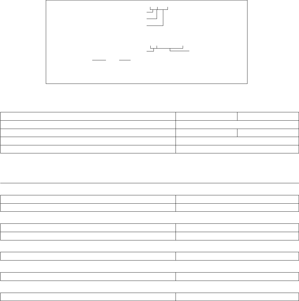
ENGINE IDENTIFICATION NUMBERS
Kohler engine identication numbers (model, specication and serial) should be referenced for efcient repair,
ordering correct parts, and engine replacement.
Model .....................XT-6
Courage Engine
Vertical Shaft
Numerical Designation
Specication ...............XT149-0001
Serial .....................4223500328
Year Manufactured Code Factory Code
Code Year
42 2012
43 2013
44 2014
GENERAL SPECIFICATIONS
3,6
XT-6, XTR-6
XT6.5, XT650,
XT6.75, XT675
XT-7, XTR-7,
XT775, XT8
Bore 65 mm (2.6 in.) 70 mm (2.8 in.)
Stroke 45 mm (1.8 in.)
Displacement 149 cc (9.1 cu. in.) 173 cc (10.6 cu. in.)
Oil Capacity (rell) 0.6 L (20 oz.)
Maximum Angle of Operation (@ full oil level)
4
20°
TORQUE SPECIFICATIONS
3,5
XT-6, XTR-6
XT6.5, XT650,
XT6.75, XT675
XT-7, XTR-7,
XT775, XT8
Air Cleaner Base
Stud Fastener 8 N·m (71 in. lb.)
Crankcase Fastener 8 N·m (71 in. lb.)
Blower Housing
Stud 10 N·m (88 in. lb.)
Nut 8 N·m (70 in. lb.)
Brake
Mounting Fastener 9.5 N·m (84 in. lb.)
Breather Cover
Fastener 10 N·m (88 in. lb.)
Carburetor
Stud Fastener 8 N·m (71 in. lb.)
3
Values are in Metric units. Values in parentheses are English equivalents.
4
Exceeding maximum angle of operation may cause engine damage from insufcient lubrication.
5
Lubricate threads with engine oil prior to assembly.
6
Any and all horsepower (hp) references by Kohler are Certied Power Ratings and per SAE J1940 & J1995 hp
standards. Details on Certied Power Ratings can be found at KohlerEngines.com.

6
Specications
KohlerEngines.com 14 690 01 Rev. G
TORQUE SPECIFICATIONS
3,5
XT-6, XTR-6
XT6.5, XT650,
XT6.75, XT675
XT-7, XTR-7,
XT775, XT8
Connecting Rod
Cap Fastener (torque in increments) 12.5 N·m (110 in. lb.)
Crankcase
Oil Drain Plug
7
13.6 N·m (120 in. lb.)
Oil Pan Screw 11.0 N·m (98 in. lb.) 14.7 N·m (130 in. lb.)
Cylinder Head
Fastener (torque in 2 increments) rst to 14 N·m (123 in. lb.)
nally to 27.8 N·m (246 in. lb.)
Flywheel
Retaining Nut 51.5 N·m (38 ft. lb.)
Fuel Tank
Bracket to Crankcase Stud 8 N·m (71 in. lb.)
Bracket to Tank Fastener 4.5 N·m (40 in. lb.)
Governor
Lever Fastener 9.5 N·m (84 in. lb.)
Gear Fastener 9.5 N·m (84 in. lb.)
Ignition
Spark Plug 27 N·m (20 ft. lb.)
Module Fastener 10 N·m (88 in. lb.)
Screw 10 N·m (88 in. lb.)
Mufer
Exhaust Stud 5.0 N·m (44 in. lb.)
Exhaust Stud Nut Fastener 9.5 N·m (84 in. lb.)
Retractable Starter
Fastener 8 N·m (71 in. lb.)
Rocker Arm
Stud 13.6 N·m (120 in. lb.)
Pivot Jam Nut 9.5 N·m (84 in. lb.)
Speed Control
Bracket Assembly Fastener 8 N·m (71 in. lb.)
Valve Cover
Fastener 8 N·m (71 in. lb.)
3
Values are in Metric units. Values in parentheses are English equivalents.
5
Lubricate threads with engine oil prior to assembly.
7
Apply thread sealant around three full threads before assembly. No excess sealant allowed on inside or outside of
joint. Threads with preapplied sealant do not require use of additional sealant. Approved sealants include Perma-Loc
LH 150, Perma-Loc MM 115, Perma-Loc HH 120, Perma-Loc HL 126.

7
Specications
14 690 01 Rev. G KohlerEngines.com
CLEARANCE SPECIFICATIONS
3
XT-6, XTR-6
XT6.5, XT650,
XT6.75, XT675
XT-7, XTR-7,
XT775, XT8
Camshaft
End Play 0.3/0.85 mm (0.0118/0.0335 in.)
Running Clearance 0.013/0.0555 mm (0.00051/0.00217 in.)
Connecting Rod
Connecting Rod-to-Crankpin Running Clearance
New 0.025/0.045 mm (0.0009/0.0017 in.)
Connecting Rod-to-Crankpin Side Clearance
New 0.03/0.48 mm
(0.00118/0.0189 in.)
0.13/0.58 mm
(0.0051/0.0228 in.)
Connecting Rod-to-Piston Pin Running Clearance 0.008/0.025 mm (0.0003/0.0009 in.)
Piston Pin End I.D. New @ 21°C (70°F) 13.006/13.017 mm
(0.5120/0.5125 in.)
18.006/18.017 mm
(0.7088/0.7093 in.)
Crankcase
Governor Cross Shaft Bore I.D.
New 6.000/6.024 mm (0.2362/0.2372 in.)
Crankshaft
End Play (free) 0.427/1.298 mm (0.0168/0.05110 in.)
Bore in Oil Pan I.D.
Early Models
Later Models
25.400/25.421 mm (0.9999/1.0008 in.)
27.050/27.071 mm (1.06496/1.06578 in.)
Bore in Oil Pan Running Clearance
Early Models
Later Models
0.015/0.051 mm (0.0005/0.002 in.)
0.008/0.121 mm (0.0031/0.00476 in.)
Bearing (ywheel) Journal O.D.
Early Models
Later Models
Max. Taper
Max. Out-of-Round
24.975/24.989 mm
(0.9832/0.9838 in.)
25.005/25.019 mm
(0.9844/0.9850 in.)
0.025 mm (0.0009 in.)
0.025 mm (0.0009 in.)
24.975/24.989 mm
(0.9832/0.9838 in.)
24.975/24.989 mm
(0.9832/0.9838 in.)
0.025 mm (0.0009 in.)
0.025 mm (0.0009 in.)
Bearing (PTO) Journal O.D.
Early Models
Later Models
Max. Taper
Max. Out-of-Round
25.370/25.385 mm (0.9988/0.9994 in.)
26.95/26.97 mm (1.061/1.062 in.)
0.025 mm (0.0009 in.)
0.025 mm (0.0009 in.)
Connecting Rod Journal O.D.
New
Max. Taper
Max. Out-of-Round
25.985/25.995 mm
(1.0230/1.0234 in.)
0.010 mm (0.0004 in.)
0.010 mm (0.0004 in.)
29.985/29.995 mm
(1.1805/1.1809 in.)
0.010 mm (0.0004 in.)
0.010 mm (0.0004 in.)
Cylinder Bore
Bore I.D. 65.00/65.02 mm
(2.559/2.560 in.)
70.00/70.02 mm
(2.755/2.756 in.)
Max. Out-of-Round
Max. Taper
0.0127 mm (0.0005 in.)
0.0127 mm (0.0005 in.)
Cylinder Head
Max. Out-of-Flatness 0.08 mm (0.003 in.)
3
Values are in Metric units. Values in parentheses are English equivalents.

8
Specications
KohlerEngines.com 14 690 01 Rev. G
CLEARANCE SPECIFICATIONS
3
XT-6, XTR-6
XT6.5, XT650,
XT6.75, XT675
XT-7, XTR-7,
XT775, XT8
Governor
Governor Cross Shaft -to-Crankcase Running Clearance 0.020/0.064 mm (0.0007/0.0025 in.)
Cross Shaft O.D.
New 5.96/5.98 mm (0.2346/0.2354 in.)
Gear Shaft O.D.
New 6.01/6.03 mm (0.2366/0.2374 in.)
Governor Gear Shaft-to-Governor Gear Running Clearance 0.09/0.19 mm (0.0035/0.0074 in.)
Ignition
Spark Plug Gap 0.76 mm (0.030 in.)
Module Air Gap 0.254 mm (0.010 in.)
Piston, Piston Rings, and Piston Pin
Pin Bore I.D. 13.002/13.008 mm
(0.5118/0.5121 in.)
18.000/18.008 mm
(0.7086/0.7089 in.)
Pin O.D. 12.990/12.996 mm
(0.5114/0.5116 in.)
17.990/17.996 mm
(0.7082/0.7085 in.)
Top and Center Compression Ring Side Clearance
New Bore, Before Serial No. 40244XXXXX
New Bore, After Serial No. 40243XXXXX
0.02/0.06 mm (0.0007/0.0023 in.)
0.001/0.020 mm (0.00004/0.00080 in.)
Top and Center Compression Ring End Gap
New Bore, Before Serial No. 40244XXXXX
Top and Center
New Bore, After Serial No. 40243XXXXX
Top
Center
0.25/0.40 mm
(0.0098/0.0157 in.)
0.1/0.25 mm
(0.0039/0.0098 in.)
0.61/0.76 mm
(0.0240/0.0299 in.)
0.25/0.40 mm
(0.0098/0.0157 in.)
0.1/0.25 mm
(0.0039/0.0098 in.)
0.3/0.5 mm
(0.0118/0.0197 in.)
Thrust Face O.D. 64.975/64.985 mm
(0.2558/0.2558 in.)
69.960/69.980 mm
(2.7543/2.7551 in.)
Piston Thrust Face-to-Cylinder Bore Running Clearance 0.025/0.035 mm
(0.0010/0.0014 in.)
0.020/0.060 mm
(0.0007/0.0024 in.)
Valves and Valve Lifters
Intake and Exhaust Valve Lash 0.0762/0.127 mm (0.003/0.005 in.)
Intake Valve Stem-to-Valve Guide Running Clearance 0.020/0.047 mm (0.0007/0.0018 in.)
Exhaust Valve Stem-to-Valve Guide Running Clearance 0.055/0.082 mm (0.0021/0.0032 in.)
Intake Valve Guide I.D. 5.500/5.512 mm (0.2165/0.2170 in.)
Intake Valve Stem Diameter 5.465/5.480 mm (0.2151/0.2157 in.)
Exhaust Valve Guide I.D. 5.500/5.512 mm (0.2165/0.2170 in.)
Exhaust Valve Stem Diameter 5.430/5.445 mm (0.2137/0.2143 in.)
Nominal Valve Face Angle 25°, 45°, 60°
3
Values are in Metric units. Values in parentheses are English equivalents.
9
Specications
14 690 01 Rev. G KohlerEngines.com
GENERAL TORQUE VALUES
Metric Fastener Torque Recommendations for Standard Applications
Property Class
Noncritical
Fasteners
Into Aluminum
Size
4.8
5.8
8.8
10.9 12.9
Tightening Torque: N·m (in. lb.) ± 10%
M4 1.2 (11) 1.7 (15) 2.9 (26) 4.1 (36) 5.0 (44) 2.0 (18)
M5 2.5 (22) 3.2 (28) 5.8 (51) 8.1 (72) 9.7 (86) 4.0 (35)
M6 4.3 (38) 5.7 (50) 9.9 (88) 14.0 (124) 16.5 (146) 6.8 (60)
M8 10.5 (93) 13.6 (120) 24.4 (216) 33.9 (300) 40.7 (360) 17.0 (150)
Tightening Torque: N·m (ft. lb.) ± 10%
M10 21.7 (16) 27.1 (20) 47.5 (35) 66.4 (49) 81.4 (60) 33.9 (25)
M12 36.6 (27) 47.5 (35) 82.7 (61) 116.6 (86) 139.7 (103) 61.0 (45)
M14 58.3 (43) 76.4 (56) 131.5 (97) 184.4 (136) 219.7 (162) 94.9 (70)
Torque Conversions
N·m = in. lb. x 0.113 in. lb. = N·m x 8.85
N·m = ft. lb. x 1.356 ft. lb. = N·m x 0.737
English Fastener Torque Recommendations for Standard Applications
Bolts, Screws, Nuts and Fasteners Assembled Into Cast Iron or Steel
Grade 2 or 5 Fasteners
Into Aluminum
Size Grade 2 Grade 5 Grade 8
Tightening Torque: N·m (in. lb.) ± 20%
8-32 2.3 (20) 2.8 (25) — 2.3 (20)
10-24 3.6 (32) 4.5 (40) — 3.6 (32)
10-32 3.6 (32) 4.5 (40) — —
1/4-20 7.9 (70) 13.0 (115) 18.7 (165) 7.9 (70)
1/4-28 9.6 (85) 15.8 (140) 22.6 (200) —
5/16-18 17.0 (150) 28.3 (250) 39.6 (350) 17.0 (150)
5/16-24 18.7 (165) 30.5 (270) — —
3/8-16 29.4 (260) — — —
3/8-24 33.9 (300) — — —
Tightening Torque: N·m (ft. lb.) ± 20%
5/16-24 — — 40.7 (30) —
3/8-16 — 47.5 (35) 67.8 (50) —
3/8-24 — 54.2 (40) 81.4 (60) —
7/16-14 47.5 (35) 74.6 (55) 108.5 (80) —
7/16-20 61.0 (45) 101.7 (75) 142.5 (105) —
1/2-13 67.8 (50) 108.5 (80) 155.9 (115) —
1/2-20 94.9 (70) 142.4 (105) 223.7 (165) —
9/16-12 101.7 (75) 169.5 (125) 237.3 (175) —
9/16-18 135.6 (100) 223.7 (165) 311.9 (230) —
5/8-11 149.5 (110) 244.1 (180) 352.6 (260) —
5/8-18 189.8 (140) 311.9 (230) 447.5 (330) —
3/4-10 199.3 (147) 332.2 (245) 474.6 (350) —
3/4-16 271.2 (200) 440.7 (325) 637.3 (470) —

Tools and Aids
10 14 690 01 Rev. GKohlerEngines.com
Certain quality tools are designed to help you perform specic disassembly, repair, and reassembly procedures. By
using these tools, you can properly service engines easier, faster, and safer! In addition, you’ll increase your service
capabilities and customer satisfaction by decreasing engine downtime.
Here is a list of tools and their source.
SEPARATE TOOL SUPPLIERS
Kohler Tools
Contact your local Kohler source of
supply.
SE Tools
415 Howard St.
Lapeer, MI 48446
Phone 810-664-2981
Toll Free 800-664-2981
Fax 810-664-8181
Design Technology Inc.
768 Burr Oak Drive
Westmont, IL 60559
Phone 630-920-1300
Fax 630-920-0011
TOOLS
Description Source/Part No.
Alcohol Content Tester
For testing alcohol content (%) in reformulated/oxygenated fuels.
Kohler 25 455 11-S
Camshaft Endplay Plate
For checking camshaft endplay.
SE Tools KLR-82405
Camshaft Seal Protector (Aegis)
For protecting seal during camshaft installation.
SE Tools KLR-82417
Cylinder Leakdown Tester
For checking combustion retention and if cylinder, piston, rings, or valves are worn.
Individual component available:
Adapter 12 mm x 14 mm (Required for leakdown test on XT-6 engines)
Kohler 25 761 05-S
Design Technology Inc.
DTI-731-03
Dealer Tool Kit (Domestic)
Complete kit of Kohler required tools.
Components of 25 761 39-S:
Ignition System Tester
Cylinder Leakdown Tester
Oil Pressure Test Kit
Rectier-Regulator Tester (120 V AC/60Hz)
Kohler 25 761 39-S
Kohler 25 455 01-S
Kohler 25 761 05-S
Kohler 25 761 06-S
Kohler 25 761 20-S
Dealer Tool Kit (International)
Complete kit of Kohler required tools.
Components of 25 761 42-S:
Ignition System Tester
Cylinder Leakdown Tester
Oil Pressure Test Kit
Rectier-Regulator Tester (240 V AC/50Hz)
Kohler 25 761 42-S
Kohler 25 455 01-S
Kohler 25 761 05-S
Kohler 25 761 06-S
Kohler 25 761 41-S
Digital Vacuum/Pressure Tester
For checking crankcase vacuum.
Individual component available:
Rubber Adapter Plug
Design Technology Inc.
DTI-721-01
Design Technology Inc.
DTI-721-10
Electronic Fuel Injection (EFI) Diagnostic Software
For Laptop or Desktop PC.
Kohler 25 761 23-S
EFI Service Kit
For troubleshooting and setting up an EFI engine.
Components of 24 761 01-S:
Fuel Pressure Tester
Noid Light
90° Adapter
In-line "T" Fitting
Code Plug, Red Wire
Code Plug, Blue Wire
Shrader Valve Adapter Hose
Kohler 24 761 01-S
Design Technology Inc.
DTI-019
DTI-021
DTI-023
DTI-035
DTI-027
DTI-029
DTI-037
Flywheel Puller
For properly removing ywheel from engine.
SE Tools KLR-82408

Tools and Aids
1114 690 01 Rev. G KohlerEngines.com
TOOLS
Description Source/Part No.
Hydraulic Valve Lifter Tool
For removing and installing hydraulic lifters.
Kohler 25 761 38-S
Ignition System Tester
For testing output on all systems, including CD.
Kohler 25 455 01-S
Inductive Tachometer (Digital)
For checking operating speed (RPM) of an engine.
Design Technology Inc.
DTI-110
Offset Wrench (K and M Series)
For removing and reinstalling cylinder barrel retaining nuts.
Kohler 52 455 04-S
Oil Pressure Test Kit
For testing/verifying oil pressure on pressure lubricated engines.
Kohler 25 761 06-S
Rectier-Regulator Tester (120 volt current)
Rectier-Regulator Tester (240 volt current)
For testing rectier-regulators.
Components of 25 761 20-S and 25 761 41-S:
CS-PRO Regulator Test Harness
Special Regulator Test Harness with Diode
Kohler 25 761 20-S
Kohler 25 761 41-S
Design Technology Inc.
DTI-031
DTI-033
Spark Advance Module (SAM) Tester
For testing SAM (ASAM and DSAM) on engines with SMART-SPARK
™
.
Kohler 25 761 40-S
Starter Servicing Kit (All Starters)
For removing and reinstalling drive retaining rings and brushes.
Individual component available:
Starter Brush Holding Tool (Solenoid Shift)
SE Tools KLR-82411
SE Tools KLR-82416
Triad/OHC Timing Tool Set
For holding cam gears and crankshaft in timed position while installing timing belt.
Kohler 28 761 01-S
Valve Guide Reamer (K and M Series)
For properly sizing valve guides after installation.
Design Technology Inc.
DTI-K828
Valve Guide Reamer O.S. (Command Series)
For reaming worn valve guides to accept replacement oversize valves. Can be used
in low-speed drill press or with handle below for hand reaming.
Kohler 25 455 12-S
Reamer Handle
For hand reaming using Kohler 25 455 12-S reamer.
Design Technology Inc.
DTI-K830
AIDS
Description Source/Part No.
Camshaft Lubricant (Valspar ZZ613) Kohler 25 357 14-S
Dielectric Grease (GE/Novaguard G661) Kohler 25 357 11-S
Dielectric Grease Loctite
®
51360
Kohler Electric Starter Drive Lubricant (Inertia Drive) Kohler 52 357 01-S
Kohler Electric Starter Drive Lubricant (Solenoid Shift) Kohler 52 357 02-S
RTV Silicone Sealant
Loctite
®
5900
®
Heavy Body in 4 oz. aerosol dispenser.
Only oxime-based, oil resistant RTV sealants, such as those listed, are approved
for use. Loctite
®
Nos. 5900
®
or 5910
®
are recommended for best sealing
characteristics.
Kohler 25 597 07-S
Loctite
®
5910
®
Loctite
®
Ultra Black 598™
Loctite
®
Ultra Blue 587™
Loctite
®
Ultra Copper 5920™
Spline Drive Lubricant Kohler 25 357 12-S
Tools and Aids
12 14 690 01 Rev. GKohlerEngines.com
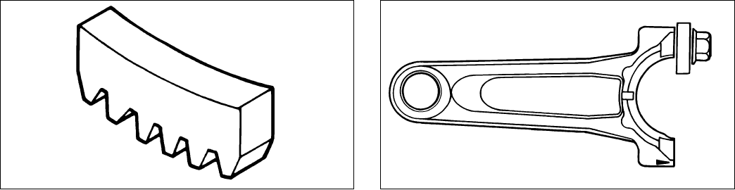
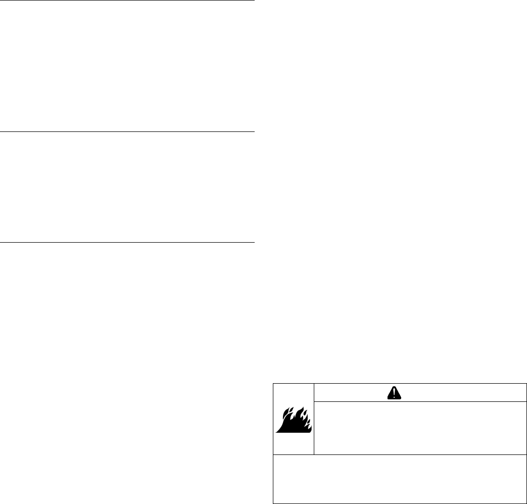
FLYWHEEL HOLDING TOOL ROCKER ARM/CRANKSHAFT TOOL
A ywheel holding tool can be made out of an old junk
ywheel ring gear and used in place of a strap wrench.
1. Using an abrasive cut-off wheel, cut out a six tooth
segment of ring gear as shown.
2. Grind off any burrs or sharp edges.
3. Invert segment and place it between ignition bosses
on crankcase so tool teeth engage ywheel ring
gear teeth. Bosses will lock tool and ywheel in
position for loosening, tightening, or removing with a
puller.
A spanner wrench to lift rocker arms or turn crankshaft
may be made out of an old junk connecting rod.
1. Find a used connecting rod from a 10 HP or larger
engine. Remove and discard rod cap.
2. Remove studs of a Posi-Lock rod or grind off
aligning steps of a Command rod, so joint surface is
at.
3. Find a 1 in. long capscrew with correct thread size to
match threads in connecting rod.
4. Use a at washer with correct I.D. to slip on
capscrew and approximately 1 in. O.D. Assemble
capscrew and washer to joint surface of rod.

1314 690 01 Rev. G KohlerEngines.com
Troubleshooting
Engine Cranks But Will Not Start
● Battery connected backwards.
● Blown fuse.
● Carburetor solenoid malfunction.
● Choke not closing.
● Clogged fuel line or fuel lter.
● Diode in wiring harness failed in open circuit mode.
● DSAI or DSAM malfunction.
● Empty fuel tank.
● Faulty electronic control unit.
● Faulty ignition coil(s).
● Faulty spark plug(s).
● Fuel pump malfunction-vacuum hose clogged or
leaking.
● Fuel shut-off valve closed.
● Ignition module(s) faulty or improperly gapped.
● Insufcient voltage to electronic control unit.
● Interlock switch is engaged or faulty.
● Key switch or kill switch in OFF position.
● Low oil level.
● Quality of fuel (dirt, water, stale, mixture).
● SMART-SPARK
TM
malfunction.
● Spark plug lead(s) disconnected.
Engine Starts But Does Not Keep Running
● Faulty carburetor.
● Faulty cylinder head gasket.
● Faulty or misadjusted choke or throttle controls.
● Fuel pump malfunction-vacuum hose clogged or
leaking.
● Intake system leak.
● Loose wires or connections that intermittently ground
ignition kill circuit.
● Quality of fuel (dirt, water, stale, mixture).
● Restricted fuel tank cap vent.
Engine Starts Hard
● Clogged fuel line or fuel lter.
● Engine overheated.
● Faulty ACR mechanism.
● Faulty or misadjusted choke or throttle controls.
● Faulty spark plug(s).
● Flywheel key sheared.
● Fuel pump malfunction-vacuum hose clogged or
leaking.
● Interlock switch is engaged or faulty.
● Loose wires or connections that intermittently ground
ignition kill circuit.
● Low compression.
● Quality of fuel (dirt, water, stale, mixture).
● Weak spark.
TROUBLESHOOTING GUIDE
When troubles occur, be sure to check simple causes which, at rst, may seem too obvious to be considered. For
example, a starting problem could be caused by an empty fuel tank.
Some general common causes of engine troubles are listed below and vary by engine specication. Use these to
locate causing factors.
Engine Will Not Crank
● Battery is discharged.
● Faulty electric starter or solenoid.
● Faulty key switch or ignition switch.
● Interlock switch is engaged or faulty.
● Loose wires or connections that intermittently ground
ignition kill circuit.
● Pawls not engaging in drive cup.
● Seized internal engine components.
Engine Runs But Misses
● Carburetor adjusted incorrectly.
● Engine overheated.
● Faulty spark plug(s).
● Ignition module(s) faulty or improperly gapped.
● Incorrect crankshaft position sensor air gap.
● Interlock switch is engaged or faulty.
● Loose wires or connections that intermittently ground
ignition kill circuit.
● Quality of fuel (dirt, water, stale, mixture).
● Spark plug lead(s) disconnected.
● Spark plug lead boot loose on plug.
● Spark plug lead loose.
Engine Will Not Idle
● Engine overheated.
● Faulty spark plug(s).
● Idle fuel adjusting needle(s) improperly set.
● Idle speed adjusting screw improperly set.
● Inadequate fuel supply.
● Low compression.
● Quality of fuel (dirt, water, stale, mixture).
● Restricted fuel tank cap vent.
Engine Overheats
● Cooling fan broken.
● Excessive engine load.
● Fan belt failed/off.
● Faulty carburetor.
● High crankcase oil level.
● Lean fuel mixture.
● Low cooling system uid level.
● Low crankcase oil level.
● Radiator, and/or cooling system components clogged,
restricted, or leaking.
● Water pump belt failed/broken.
● Water pump malfunction.
Engine Knocks
● Excessive engine load.
● Hydraulic lifter malfunction.
● Incorrect oil viscosity/type.
● Internal wear or damage.
● Low crankcase oil level.
● Quality of fuel (dirt, water, stale, mixture).
Troubleshooting
14 14 690 01 Rev. GKohlerEngines.com
Engine Loses Power
● Dirty air cleaner element.
● Engine overheated.
● Excessive engine load.
● Restricted exhaust.
● Faulty spark plug(s).
● High crankcase oil level.
● Incorrect governor setting.
● Low battery.
● Low compression.
● Low crankcase oil level.
● Quality of fuel (dirt, water, stale, mixture).
Engine Uses Excessive Amount of Oil
● Loose or improperly torqued fasteners.
● Blown head gasket/overheated.
● Breather reed broken.
● Clogged, broken, or inoperative crankcase breather.
● Crankcase overlled.
● Incorrect oil viscosity/type.
● Worn cylinder bore.
● Worn or broken piston rings.
● Worn valve stems/valve guides.
Oil Leaks from Oil Seals, Gaskets
● Breather reed broken.
● Clogged, broken, or inoperative crankcase breather.
● Loose or improperly torqued fasteners.
● Piston blow by, or leaky valves.
● Restricted exhaust.
EXTERNAL ENGINE INSPECTION
NOTE: It is good practice to drain oil at a location away
from workbench. Be sure to allow ample time for
complete drainage.
Before cleaning or disassembling engine, make a
thorough inspection of its external appearance and
condition. This inspection can give clues to what
might be found inside engines (and cause) when it is
disassembled.
● Check for buildup of dirt and debris on crankcase,
cooling ns, grass screen, and other external surfaces.
Dirt or debris on these areas can cause overheating.
● Check for obvious fuel and oil leaks, and damaged
components. Excessive oil leakage can indicate a
clogged or inoperative breather, worn or damaged
seals or gaskets, or loose fasteners.
● Check air cleaner cover and base for damage or
indications of improper t and seal.
● Check air cleaner element. Look for holes, tears,
cracked or damaged sealing surfaces, or other
damage that could allow unltered air into engine. A
dirty or clogged element could indicate insufcient or
improper maintenance.
● Check carburetor throat for dirt. Dirt in throat is further
indication that air cleaner was not functioning properly.
● Check if oil level is within operating range on dipstick.
If it is above, sniff for gasoline odor.
● Check condition of oil. Drain oil into a container; it
should ow freely. Check for metal chips and other
foreign particles.
Sludge is a natural by-product of combustion; a small
accumulation is normal. Excessive sludge formation
could indicate over rich fuel settings, weak ignition,
overextended oil change interval or wrong weight or
type of oil was used.
CLEANING ENGINE
WARNING
Cleaning Solvents can cause severe injury or
death.
Use only in well ventilated areas away from
ignition sources.
Carburetor cleaners and solvents are extremely
ammable. Follow cleaner manufacturer’s warnings
and instructions on its proper and safe use. Never use
gasoline as a cleaning agent.
After inspecting external condition of engine, clean
engine thoroughly before disassembly. Clean individual
components as engine is disassembled. Only clean
parts can be accurately inspected and gauged for wear
or damage. There are many commercially available
cleaners that will quickly remove grease, oil, and grime
from engine parts. When such a cleaner is used, follow
manufacturer’s instructions and safety precautions
carefully.
Make sure all traces of cleaner are removed before
engine is reassembled and placed into operation. Even
small amounts of these cleaners can quickly break down
lubricating properties of engine oil.
1514 690 01 Rev. G KohlerEngines.com
Troubleshooting
Condition Conclusion
Crankcase breather clogged or inoperative. NOTE: If breather is integral part of valve cover and
cannot be serviced separately, replace valve
cover and recheck pressure.
Disassemble breather, clean parts thoroughly, check
sealing surfaces for atness, reassemble, and recheck
pressure.
Seals and/or gaskets leaking. Loose or improperly torque
fasteners.
Replace all worn or damaged seals and gaskets. Make
sure all fasteners are tightened securely. Use appropriate
torque valves and sequences when necessary.
Piston blow by or leaky valves (conrm by inspecting
components).
Recondition piston, rings, cylinder bore, valves and
valves guides.
Restricted exhaust. Check exhaust screen/spark arrestor (if equipped). Clean
or replace as needed. Repair or replace any other
damaged/restricted mufer or exhaust system parts.
CRANKCASE VACUUM TEST
WARNING
Carbon Monoxide can cause severe nausea,
fainting or death.
Avoid inhaling exhaust fumes.
Engine exhaust gases contain poisonous carbon
monoxide. Carbon monoxide is odorless, colorless,
and can cause death if inhaled.
To test crankcase vacuum with manometer:
1. Insert rubber stopper into oil ll hole. Be sure pinch
clamp is installed on hose and use tapered adapters
to connect hose between stopper and one
manometer tube. Leave other tube open to
atmosphere. Check that water level in manometer is
at 0 line. Make sure pinch clamp is closed.
2. Start engine and run no-load high speed.
3. Open clamp and note water level in tube.
Level in engine side should be a minimum of 10.2
cm (4 in.) above level in open side.
If level in engine side is less than specied (low/no
vacuum), or level in engine side is lower than level in
open side (pressure), check for conditions in table
below.
4. Close pinch clamp before stopping engine.
To test crankcase vacuum with vacuum/pressure gauge:
1. Remove dipstick or oil ll plug/cap.
2. Install adapter into oil ll//dipstick tube opening,
upside down over end of a small diameter dipstick
tube, or directly into engine if a tube is not used.
Insert barbed gauge tting into hole in stopper.
3. Run engine and observe gauge reading.
Analog tester–needle movement to left of 0 is a
vacuum, and movement to right indicates a pressure.
Digital tester–depress test button on top of tester.
Crankcase vacuum should be a minimum of 10.2 cm
(4 in.) of water. If reading is below specication, or if
pressure is present, check table below for possible
causes and conclusions.
WARNING
Rotating Parts can cause severe injury.
Stay away while engine is in operation.
Keep hands, feet, hair, and clothing away from all
moving parts to prevent injury. Never operate engine
with covers, shrouds, or guards removed.
A partial vacuum should be present in crankcase when engine is operating. Pressure in crankcase (normally caused
by a clogged or improperly assembled breather) can cause oil to be forced out at oil seals, gaskets, or other available
spots.
Crankcase vacuum is best measured with either a water manometer or a vacuum gauge. Complete instructions are
provided in kits.

Troubleshooting
16 14 690 01 Rev. GKohlerEngines.com
COMPRESSION TEST
For Command Twins:
A compression test is best performed on a warm engine. Clean any dirt or debris away from base of spark plug(s)
before removing them. Be sure choke is off, and throttle is wide open during test. Compression should be at least 160
psi and should not vary more than 15% between cylinders.
All other models:
These engines are equipped with an automatic compression release (ACR) mechanism. It is difcult to obtain an
accurate compression reading because of ACR mechanism. As an alternative, use cylinder leakdown test described
below.
CYLINDER LEAKDOWN TEST
A cylinder leakdown test can be a valuable alternative to a compression test. By pressurizing combustion chamber
from an external air source you can determine if valves or rings are leaking, and how badly.
Cylinder leakdown tester is a relatively simple, inexpensive leakdown tester for small engines. This tester includes a
quick-connect for attaching adapter hose and a holding tool.
1. Run engine for 3-5 minutes to warm it up.
2. Remove spark plug(s) and air lter from engine.
3. Rotate crankshaft until piston (of cylinder being tested) is at top dead center (TDC) of compression stroke. Hold
engine in this position while testing. Holding tool supplied with tester can be used if PTO end of crankshaft is
accessible. Lock holding tool onto crankshaft. Install a 3/8 in. breaker bar into hole/slot of holding tool, so it is
perpendicular to both holding tool and crankshaft PTO.
If ywheel end is more accessible, use a breaker bar and socket on ywheel nut/screw to hold it in position. An
assistant may be needed to hold breaker bar during testing. If engine is mounted in a piece of equipment, it may
be possible to hold it by clamping or wedging a driven component. Just be certain that engine cannot rotate off of
TDC in either direction.
4. Install adapter into spark plug hole, but do not attach it to tester at this time.
5. Turn regulator knob completely counterclockwise.
6. Connect an air source of at least 50 psi to tester.
7. Turn regulator knob clockwise (increase direction) until gauge needle is in yellow set area at low end of scale.
8. Connect tester quick-connect to adapter hose. While rmly holding engine at TDC, gradually open tester valve.
Note gauge reading and listen for escaping air at combustion air intake, exhaust outlet, and crankcase breather.
Condition Conclusion
Air escaping from crankcase breather. Ring or cylinder worn.
Air escaping from exhaust system. Defective exhaust valve/improper seating.
Air escaping from intake. Defective intake valve/improper seating.
Gauge reading in low (green) zone. Piston rings and cylinder in good condition.
Gauge reading in moderate (yellow) zone. Engine is still usable, but there is some wear present.
Customer should start planning for overhaul or
replacement.
Gauge reading in high (red) zone. Rings and/or cylinder have considerable wear. Engine
should be reconditioned or replaced.
17
Air Cleaner/Intake
14 690 01 Rev. G KohlerEngines.com
AIR CLEANER
These systems are CARB/EPA certied and components
should not be altered or modied in any way.
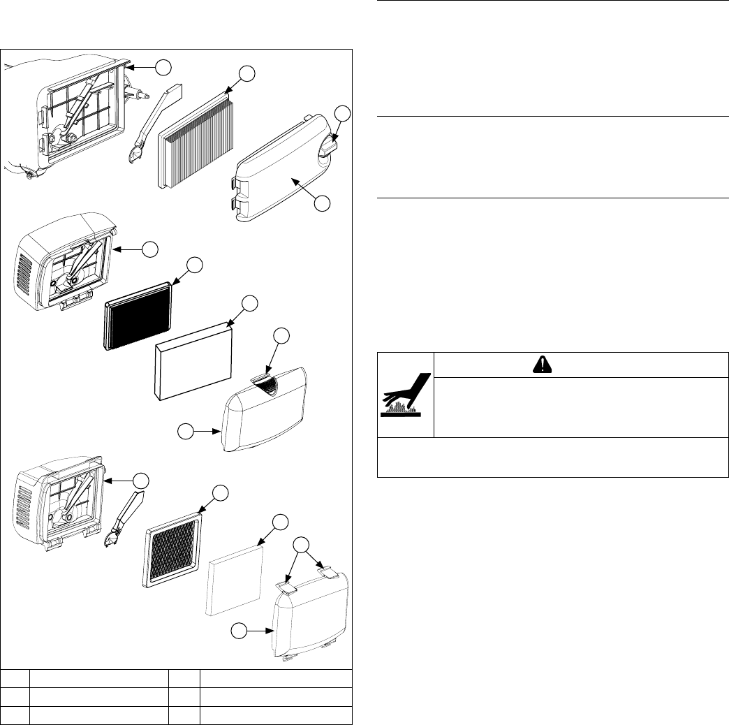
Air Cleaner Components
D
E
A
C
A
F
B
D
C
D
C
B
A
F
A Air Cleaner Cover B Precleaner
C Paper Element D Base
E Air Cleaner Knob F Air Cleaner Latch
NOTE: Operating engine with loose or damaged air
cleaner components could cause premature
wear and failure. Replace all bent or damaged
components.
NOTE: Paper element cannot be blown out with
compressed air.
Loosen knob or unhook latch and remove air cleaner
cover.
Precleaner (if equipped)
1. Remove precleaner.
2. Replace or wash precleaner in warm water with
detergent. Rinse and allow to air dry.
3. Reinstall precleaner into cover, aligning hole in
precleaner with upper cover knob.
Paper Element
1. Remove paper element from base and replace.
2. Install element with pleated side out and seat rubber
seal onto edges of base.
Foam Element
1. Remove foam element from base and replace.
2. Install element with foam side out and seat rubber
seal onto edges of base.
Reinstall air cleaner cover and secure with knob or latch.
BREATHER TUBE
Make sure both ends of breather tube are properly
connected.
AIR COOLING
WARNING
Hot Parts can cause severe burns.
Do not touch engine while operating or just
after stopping.
Never operate engine with heat shields or guards
removed.
Proper cooling is essential. To prevent over heating,
clean screens, cooling ns, and other external surfaces
of engine. Avoid spraying water at wiring harness or any
electrical components. Refer to Maintenance Schedule.

18
Fuel System
KohlerEngines.com 14 690 01 Rev. G
Typical carbureted fuel system and related components
include:
● Fuel tank.
● Fuel line.
● In-line fuel lter.
● Fuel tank lter (in-nipple).
● Fuel shut-off valve (if equipped).
● Carburetor.
Fuel tank outlet is located above carburetor inlet,
allowing gravity to feed fuel through in-line lter and fuel
line to carburetor.
Fuel enters carburetor through fuel shut-off valve and
sediment bowl and then goes to carburetor oat bowl.
Fuel is drawn into carburetor body and mixed with air.
This fuel-air mixture is then burned in engine combustion
chamber.
FUEL RECOMMENDATIONS
Refer to Maintenance.
FUEL LINE
Low permeation fuel line must be installed on carbureted
Kohler Co. engines to maintain EPA and CARB
regulatory compliance.
FUEL SHUT-OFF (if equipped)
Some engines are equipped with a fuel shut-off located
at carburetor. It controls fuel ow from tank to carburetor.
FUEL SYSTEM TESTS
When engine starts hard, or turns over but will not start, fuel system might be causing problems. Test fuel system by
performing following tests.
1. Check for fuel in combustion chamber.
a. Disconnect and ground spark plug lead.
b. Close choke on carburetor.
c. Crank engine several times.
d. Remove spark plug and check for fuel at tip.
2. Check for fuel ow from tank to carburetor.
a. Remove fuel line from inlet tting of carburetor.
b. Use an approved fuel container to catch fuel, and
hold line below bottom of tank to observe fuel
ow.
3. Check operation of fuel shut-off valve.
a. Remove fuel sediment bowl under inlet tting of
carburetor.
b. Turn fuel shut-off valve ON and OFF and observe
operation.
Condition Conclusion
Fuel at tip of spark plug. Fuel is reaching combustion chamber.
No fuel at tip of spark plug. Check fuel ow from fuel tank (step 2).
Fuel ows from fuel line. Check operation of fuel shut-off valve (step 3).
No fuel ow from fuel line. Check fuel tank vent, in-line lter threaded into tank, and
fuel line. Correct any observed problem and reconnect
line.
Fuel ows from valve. Check for dirt and water in sediment bowl and screen.
Clean bowl and screen as needed. Check for faulty
carburetor, refer to Carburetor.
No fuel ows from valve. Check for a restriction in fuel shut-off valve or inlet elbow.
19
Fuel System
14 690 01 Rev. G KohlerEngines.com
CARBURETOR
WARNING
Gasoline is extremely ammable and its vapors can
explode if ignited. Store gasoline only in approved
containers, in well ventilated, unoccupied buildings, away
from sparks or ames. Spilled fuel could ignite if it comes
in contact with hot parts or sparks from ignition. Never use
gasoline as a cleaning agent.
Explosive Fuel can cause res and severe
burns.
Do not ll fuel tank while engine is hot or
running.
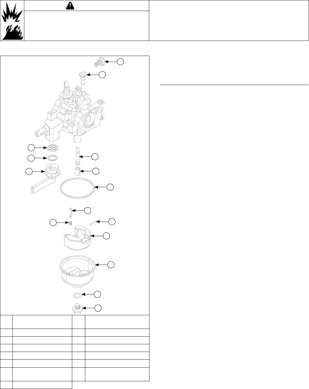
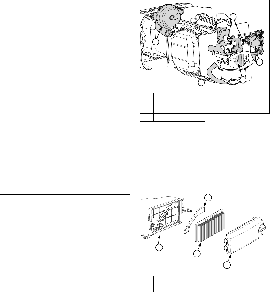
Typical One-Barrel Carburetor Components
A
B
F
G
H
I
K
M
L
N
O
J
C
E
D
A
Low Idle Speed
Adjusting Screw
B Idle Jet
C Fuel Shut-Off Gasket D Wave Washer
E Fuel Shut-Off Valve F Main Nozzle Tube
G Main Jet H Bowl Gasket
I Fuel Inlet Needle J Spring
K Hinge Pin L Float
M Fuel Bowl N
Bowl Retaining Screw
Gasket
O Bowl Retaining Screw
These engines are equipped with a xed main jet
carburetor. Carburetor is designed to deliver correct fuel-
to-air mixture to engine under all operating conditions.
Idle mixture is set at factory and cannot be adjusted.
Troubleshooting Checklist
When engine starts hard, runs rough, or stalls at low
idle speed, check these areas before adjusting or
disassembling carburetor.
1. Make sure fuel tank is lled with clean, fresh
gasoline.
2. Make sure fuel tank cap vent is not blocked and is
operating properly.
3. Make sure fuel is reaching carburetor. This includes
checking fuel shut-off valve, fuel tank lter screen,
in-line fuel lter, fuel lines and fuel pump for
restrictions or faulty components as necessary.
4. Make sure air cleaner base and carburetor are
securely fastened to engine using gaskets in good
condition.
5. Make sure air cleaner element (including precleaner
if equipped) is clean and all air cleaner components
are fastened securely.
6. Make sure ignition system, governor system,
exhaust system, and throttle and choke controls are
operating properly.
20
Fuel System
KohlerEngines.com 14 690 01 Rev. G
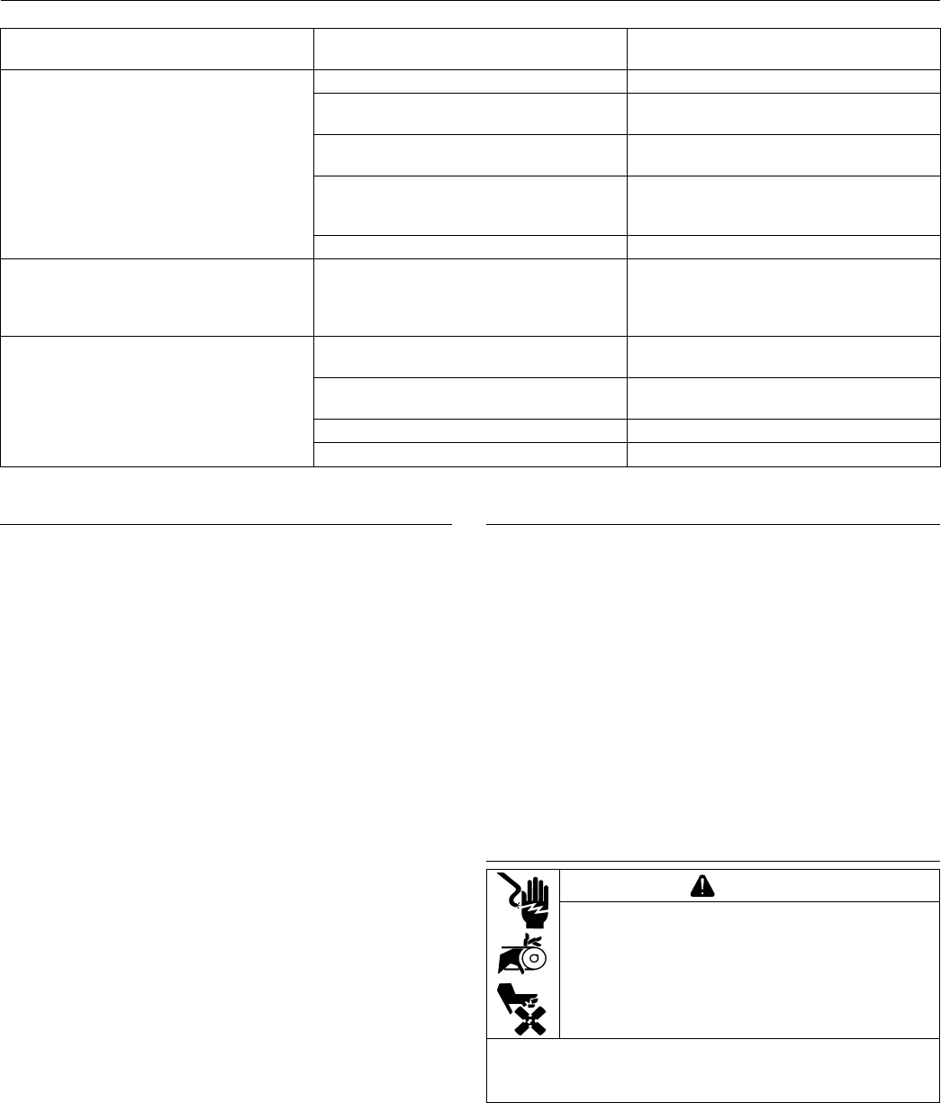
Troubleshooting-Carburetor Related Causes
Condition Possible Cause Conclusion
Engine starts hard, runs rough, or
stalls at idle speed.
Low idle fuel mixture (some models)/
speed improperly adjusted.
Adjust idle speed screw or clean
carburetor.
Engine runs rich (indicated by black,
sooty exhaust smoke, misring, loss
of speed and power, governor
hunting, or excessive throttle
opening).
Clogged air cleaner. Clean or replace air cleaner.
Choke partially closed during
operation.
Check choke lever/linkage to ensure
choke is operating properly.
Dirt under fuel inlet needle. Remove needle; clean needle and
seat and blow with compressed air.
Bowl vent or air bleeds plugged. Clean vent, ports, and air bleeds.
Blow out all passages with
compressed air.
Leaky, cracked, or damaged oat. Submerge oat to check for leaks.
Engine runs lean (indicated by
misring, loss of speed and power,
governor hunting, or excessive
throttle opening).
Idle holes plugged; dirt in fuel delivery
channels.
Clean main fuel jet and all passages;
blow out with compressed air.
Fuel leaks from carburetor. Float damaged. Submerge oat to check for leaks.
Replace oat.
Dirt under fuel inlet needle. Remove needle; clean needle and
seat and blow with compressed air.
Bowl vents plugged. Blow out with compressed air.
Carburetor bowl gasket leaks. Replace gasket.
Carburetor Circuits
Float
Fuel level in bowl is maintained by oat and fuel inlet
needle. Buoyant force of oat stops fuel ow when
engine is at rest. When fuel is being consumed, oat will
drop and fuel pressure will push inlet needle away from
seat, allowing more fuel to enter bowl. When demand
ceases, buoyant force of oat will again overcome fuel
pressure, rising to predetermined setting and stop ow.
Slow and Mid-Range
At low speeds engine operates only on slow circuit. As
a metered amount of air is drawn through slow air bleed
jets, fuel is drawn through main jet and further metered
through slow jet. Air and fuel are mixed in body of slow
jet and exit to idle progression (transfer port) chamber.
From idle progression chamber, air fuel mixture is
metered through idle port passage. At low idle air/fuel
mixture is controlled by setting of idle fuel adjusting
screws. This mixture is then mixed with main body of
air and delivered to engine. As throttle plate opening
increases, greater amounts of air/fuel mixture are drawn
in through xed and metered idle progression holes.
As throttle plate opens further, vacuum signal becomes
great enough at venturi so main circuit begins to work.
Main (high-speed)
At high speeds/loads engine operates on main circuit.
As a metered amount of air is drawn through air jet,
fuel is drawn through main jet. Air and fuel are mixed
in main nozzles then enters main body of airow where
further mixing of fuel and air occurs. This mixture is then
delivered to combustion chamber. Carburetor has a xed
main circuit; no adjustment is possible.
Carburetor Adjustments
NOTE: Carburetor adjustments should be made only
after engine has warmed up.
Carburetor is designed to deliver correct fuel-to-air
mixture to engine under all operating conditions. Main
fuel jet is calibrated at factory and is not adjustable. Idle
fuel adjusting needles are also set at factory and are not
adjustable.
Low Idle Speed (RPM) Adjustment
NOTE: Actual low idle speed depends on application.
Refer to equipment manufacturer’s
recommendations. Low idle speed for basic
engines is 1800 RPM.
Place throttle control into idle or slow position. Turn low
idle speed adjusting screw in or out to obtain allow idle
speed of 1800 RPM (± 75 RPM).
Carburetor Servicing
WARNING
Accidental Starts can cause severe injury or
death.
Disconnect and ground spark plug lead(s)
before servicing.
Before working on engine or equipment, disable
engine as follows: 1) Disconnect spark plug lead(s). 2)
Disconnect negative (–) battery cable from battery.
NOTE: Main and slow jets are xed and size specic
and can be removed if required. Fixed jets for
high altitudes are available.
21
Fuel System
14 690 01 Rev. G KohlerEngines.com
● Inspect carburetor body for cracks, holes, and other
wear or damage.
● Inspect oat for cracks, holes, and missing or
damaged oat tabs. Check oat hinge and shaft for
wear or damage.
● Inspect fuel inlet needle and seat for wear or damage.
1. Perform removal procedures for appropriate air
cleaner and carburetor outlined in Disassembly.
2. Clean exterior surfaces of dirt or foreign material
before disassembling carburetor. Remove bowl
retaining screws, and carefully separate fuel bowl
from carburetor. Do not damage fuel bowl O-rings.
Transfer any remaining fuel into an approved
container. Save all parts. Fuel can also be drained
prior to bowl removal by loosening/removing bowl
drain screw.
3. Remove oat pin and inlet needle. Seat for inlet
needle is not serviceable and should not be
removed.
4. Clean carburetor bowl and inlet seat areas as
required.
5. Carefully remove main jet from carburetor. After
main jet is removed, main nozzles can be removed
through bottom of main towers. Note orientation/
direction of nozzles. End with 2 raised shoulders
should be out/down adjacent to main jets.
6. Save parts for cleaning and reuse unless a jet kit is
also being installed. Clean slow jets using
compressed air or carburetor cleaner, do not use
wire.
NOTE: There are 2 O-rings on body of idle jet.
Carburetor is now disassembled for appropriate cleaning
and installation of parts in overhaul kit. See instructions
provided with repair kits for more detailed information.
High Altitude Operation
Engines may require a high altitude carburetor kit to
ensure correct engine operation at altitudes above 1219
meters (4000 ft.). To obtain high altitude kit information
or to nd a Kohler authorized dealer visit KohlerEngines.
com or call 1-800-544-2444 (U.S. and Canada).
This engine should be operated in its original
conguration below 1219 meters (4000 ft.) as damage
may occur if high altitude carburetor kit is installed and
operated below 1219 meters (4000 ft.).
Auto Choke Troubleshooting (if equipped)
If engine is equipped with auto choke, identify design
and follow appropriate troubleshooting procedure.
NOTE: Procedures may be easier to perform with
engine cover removed. Refer to Disassembly/
Inspection and Service and Reassembly
procedure.
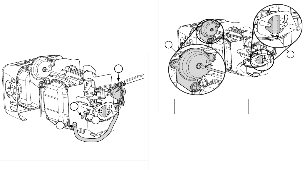
Auto Choke Components - Vacuum/Diaphragm
Design
A
B
E
C
D
A
Bimetallic Spring
Housing
B Linkage
C Diaphragm Assembly D Choke Plate
E Vacuum Hose
A bimetallic spring reacts to mufer heat and moves
linkage that opens or closes choke. A diaphragm that
operates from intake manifold vacuum assists spring
system. These two elements work together to operate
a smooth choke system that facilitates easy reliable
starting.
Use following procedures to troubleshoot vacuum/
diaphragm design auto choke system and its
components. These procedures are to be performed on
a cold engine.
Cover, Element, and Breather Cover
C
A
B
D
A Air Cleaner Cover B Element
C Breather Cover D Air Cleaner Base
1. Remove air cleaner cover, air cleaner, and breather
cover from air cleaner base.
2. Check choke linkage for binding or debris build up.
Gently actuate linkage and observe that choke plate
has full range of movement (open and close).
22
Fuel System
KohlerEngines.com 14 690 01 Rev. G
3. Remove vacuum hose from carburetor vacuum
tting. Attach a vacuum gauge or manometer to
carburetor vacuum tting. Run engine while holding
choke plate open. Gauge should indicate a vacuum
with a minimum of 15" of water. If reading is correct,
check again for binding of restricted linkage.
4. If vacuum indicated is less than 15" of water,
problem is not an auto choke issue.
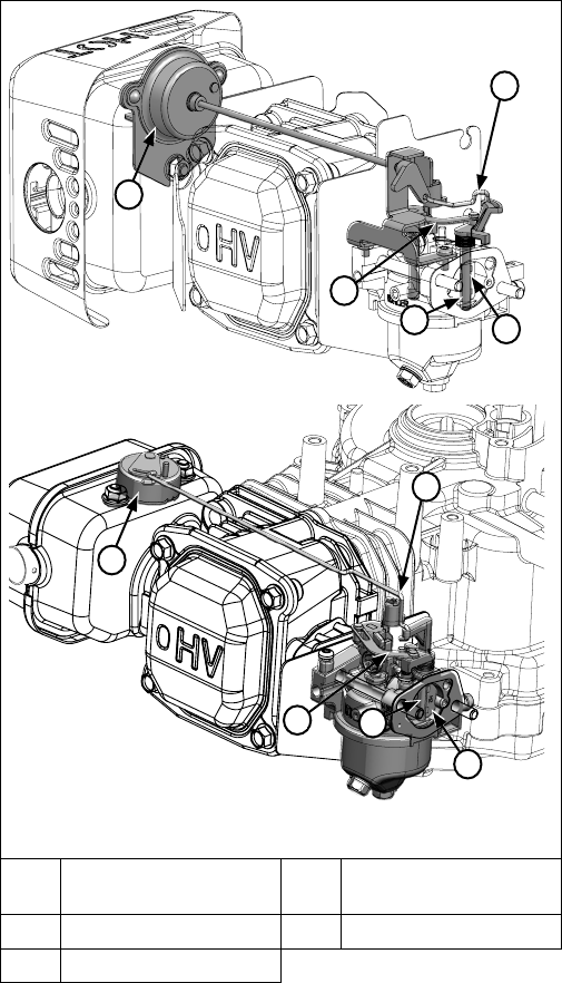
Diaphragm Assembly and Hose
A
B
C
D
A Choke Plate B Vacuum Hose
C Vacuum Fitting D Diaphragm Assembly
5. Note position of choke plate. Attach a vacuum pump
to vacuum hose. Choke plate should open 1/2 to 3/4
under vacuum and with a minimum of 15" of water. If
diaphragm assembly is unable to open choke plate,
check hose for cracks, leaks, or restrictions. If
necessary replace vacuum hose. If hose is in
working condition and choke plate fails to open with
specied vacuum, or diaphragm fails to hold choke
plate open for a minimum of 3 seconds, replace
diaphragm assembly.
6. Attach vacuum hose to carburetor vacuum tting.
7. Start engine. Upon start up choke plate should be
1/2 to 3/4 open. Choke plate should gradually
change to full open position after 2 to 2-1/2 minutes
of running. This action is performed by bimetallic
spring assembly being heated. If choke plate fails to
open, recheck linkage for binding. If necessary
replace bimetallic spring assembly.
NOTE: Inspect to ensure choke linkage is not binding.
Choke Plate and Bimetallic Spring Housing
A
B
A Choke Plate B
Bimetallic Spring
Assembly
23
Fuel System
14 690 01 Rev. G KohlerEngines.com
Auto Choke Components - Link Design
A
B
C
E
D
A
B
C
D
E
A
Bimetallic Spring
Housing
B Wire Choke Linkage
C Choke Plate D Choke Lever
E Choke Link
When engine is cold, spring around base of choke shaft
holds choke closed for starting. When engine starts,
governor closes throttle from wide open to set governor
speed. As throttle closes, link between throttle and choke
operates choke to a slightly open position. After engine
warms up, bimetallic spring overcomes choke shaft
spring force and holds choke completely open.
Use these steps to check function of link design auto
choke.
1. Remove air cleaner cover and element.
2. Choke plate should be fully close when engine is
cold.
3. There should be light spring tension holding choke
closed.
4. There should not be any binding when choke shaft
assembly is rotated, which could cause choke to
remain partially open.
5. When engine is started, choke plate should be 1/3
open. Choke plate should start to open and be
completely open within 2 to 3 minutes at room
temperature.
6. Reinstall air cleaner element and secure cover.
24
Governor System
KohlerEngines.com 14 690 01 Rev. G
Governed speed setting is determined by position of
throttle control. It can be variable or constant, depending
on engine application.
Governor is designed to hold engine speed constant
under changing load conditions. Most engines are
equipped with a centrifugal yweight mechanical
governor. Governor gear/yweight mechanism of
mechanical governor is mounted inside crankcase and is
driven off gear on camshaft.
This governor design works as follows:
● Centrifugal force acting on rotating governor gear
assembly causes yweights to move outward as
speed increases. Governor spring tension moves
them inward as speed decreases.
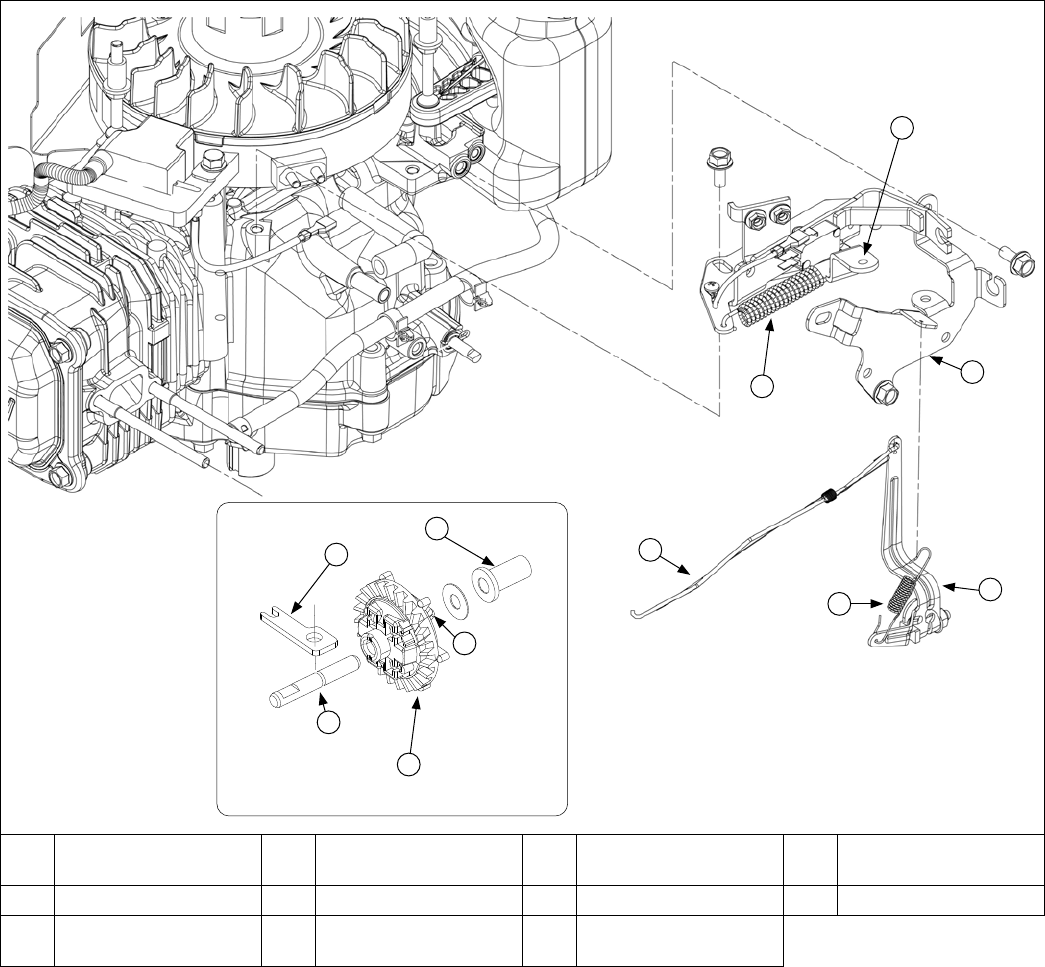
GOVERNOR
Governor Components
E
C
D
I
J
F
A
B
G
K
H
A Control Spring B
Intermediate Control
Lever
C Control Bracket D Governor Lever
E Compression Spring F Linkage G Regulating Pin H Flyweight(s)
I Governor Gear J Governor Gear Shaft K
Governor Shaft
Retainer
● As yweights move outward, they cause regulating pin
to move outward.
● Regulating pin contacts tab on cross shaft causing
shaft to rotate.
● One end of cross shaft protrudes through crankcase.
Rotating action of cross shaft is transmitted to throttle
lever of carburetor through external throttle linkage.
● When engine is at rest, and throttle is in fast position,
tension of governor spring holds throttle plate open.
When engine is operating, governor gear assembly is
rotating. Force applied by regulating pin against cross
shaft tends to close throttle plate. Governor spring
tension and force applied by regulating pin balance
each other during operation, to maintain engine
speed.

25
Governor System
14 690 01 Rev. G KohlerEngines.com
● When load is applied and engine speed and governor
gear speed decreases, governor spring tension moves
governor arm to open throttle plate wider. This allows
more fuel into engine, increasing engine speed. As
speed reaches governed setting, governor spring
tension and force applied by regulating pin will again
offset each other to hold a steady engine speed.
Initial Governor Adjustment
Make this initial adjustment whenever governor arm is
loosened or removed from cross shaft. To ensure proper
adjustment, make sure throttle linkage is connected to
both governor arm and throttle lever on carburetor.
1. Loosen governor lever adjustment screw.
2. Move governor lever away from carburetor (wide
open throttle). Do not apply excess force that may
ex or distort throttle link.
3. Grasp cross shaft with a pliers and turn shaft
clockwise as far as it will go. Then torque nut to
9.5 N·m (84 in. lb.).
4. Rotate governor shaft clockwise until it stops.
5. Hold both in this position and torque governor lever
bolt to 10 N·m (88.5 in. lb.).
26
Lubrication System
KohlerEngines.com 14 690 01 Rev. G
These engines use a splash lubrication system, supplying necessary lubrication to crankshaft, camshaft, connecting
rod, and valve train components.
Lubrication Components
OIL RECOMMENDATIONS
Refer to Maintenance.
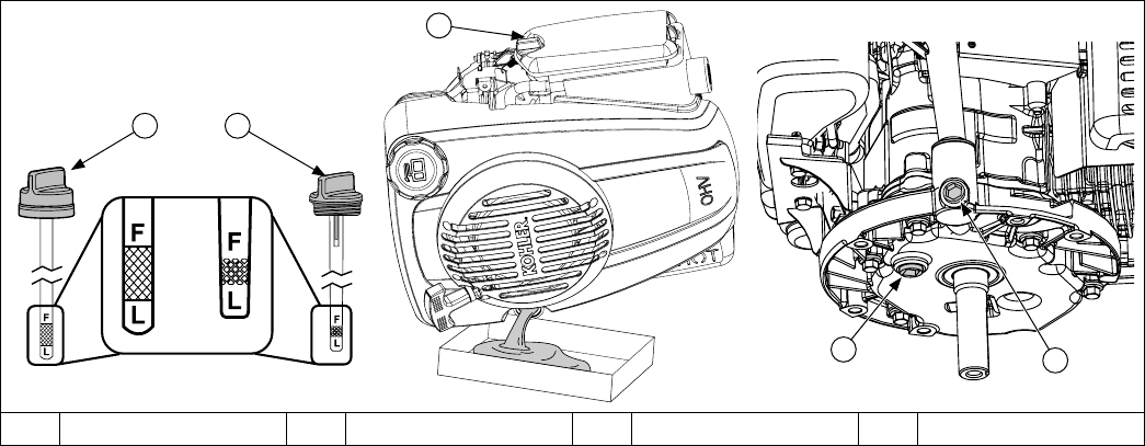
CHECK OIL LEVEL
NOTE: To prevent extensive engine wear or damage,
never run engine with oil level below or above
operating range indicator on dipstick.
Ensure engine is cool. Clean oil ll cap/dipstick areas of
any debris.
1. Remove dipstick; wipe oil off.
a. 1/4 turn cap: reinsert dipstick into tube; press
completely down and turn 1/4 turn.
or
b. Threaded cap: reinsert dipstick into tube; rest cap
on tube, do not thread cap onto tube.
2. Remove dipstick; check oil level. Level should be at
top of indicator on dipstick.
3. If oil is low on indicator, add oil up to top of indicator
mark.
4. Reinstall and secure dipstick.
CHANGE OIL
Change oil while engine is warm.
Dipstick tube
1. Clean area around oil ll cap/dipstick.
2. Remove oil ll cap/dipstick. Tilt engine on its side
with air cleaner facing up. Drain oil into appropriate
container.
3. After crankcase is drained completely, tilt engine
upright.
4. Fill crankcase with new oil. Level should be at top of
indicator on dipstick.
5. Reinstall oil ll cap/dipstick and tighten securely.
6. Dispose of used oil in accordance with local
ordinances.
Crankcase plug
1. Disable engine by disconnecting spark plug.
2. Clean area around oil ll cap/dipstick. Remove oil ll
cap/dipstick.
3. Remove crankcase plug on bottom of engine; drain
oil into appropriate container.
4. Apply thread sealant around three full threads of
drain plug; reinstall drain plug. Torque drain plug to
13.6 N·m (120 in. lb.).
5. Fill crankcase with new oil. Level should be at top of
indicator on dipstick.
6. Reinstall oil ll cap/dipstick and tighten securely.
7. Dispose of used oil in accordance with local
ordinances.
A 1/4 Turn Cap B Threaded Cap C Air Cleaner D Crankcase Plugs
A B
C
D
D
27
Electrical System
14 690 01 Rev. G KohlerEngines.com
SPARK PLUGS
CAUTION
Electrical Shock can cause injury.
Do not touch wires while engine is running.
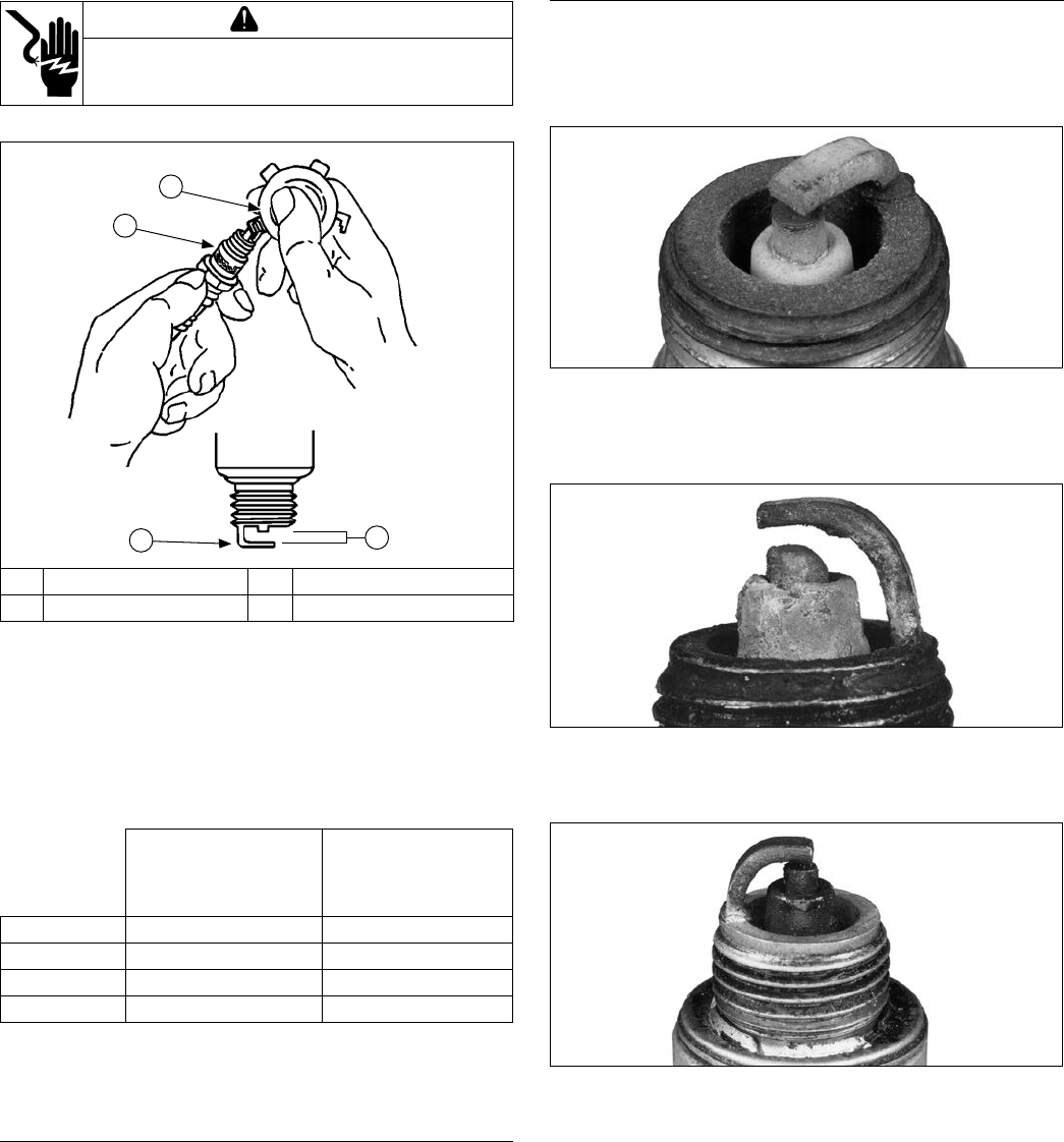
Spark Plug Component and Details
B
A
C
D
A Wire Gauge B Spark Plug
C Ground Electrode D Gap
NOTE: Do not clean spark plug in a machine using
abrasive grit. Some grit could remain in spark
plug and enter engine causing extensive wear
and damage.
Engine misre or starting problems are often caused
by a spark plug that has improper gap or is in poor
condition.
Engine is equipped with following spark plugs:
XT-6, XTR-6,
XT6.5, XT6.75,
XT650, XT675,
XT775, XT8*
XT-7, XTR-7,
XT8*
Gap 0.76 mm (0.03 in.) 0.76 mm (0.03 in.)
Thread Size 12 mm 14 mm
Reach 19.1 mm (3/4 in.) 19.1 mm (3/4 in.)
Hex Size 18 mm (3/4 in.) 15.9 mm (5/8 in.)
Refer to Maintenance for Repairs/Service Parts.
*Order replacement spark plug based on size in XT8
engine being serviced.
Service
Clean out spark plug recess. Remove plug and replace.
1. Check gap using wire feeler gauge. Adjust gap to
0.76 mm (0.03 in.).
2. Install plug into cylinder head.
3. Torque plug to 27 N·m (20 ft. lb.).
Inspection
Inspect each spark plug as it is removed from cylinder
head. Deposits on tip are an indication of general
condition of piston rings, valves, and carburetor.
Normal and fouled plugs are shown in following photos:
Normal
Plug taken from an engine operating under normal
conditions will have light tan or gray colored deposits. If
center electrode is not worn, plug can be set to proper
gap and reused.
Worn
On a worn plug, center electrode will be rounded and
gap will be greater than specied gap. Replace a worn
spark plug immediately.
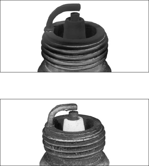
Wet Fouled
A wet plug is caused by excess fuel or oil in combustion
chamber. Excess fuel could be caused by a restricted air
cleaner, a carburetor problem, or operating engine with
too much choke. Oil in combustion chamber is usually
caused by a restricted air cleaner, a breather problem,
worn piston rings, or valve guides.
28
Electrical System
KohlerEngines.com 14 690 01 Rev. G
Carbon Fouled
Soft, sooty, black deposits indicate incomplete
combustion caused by a restricted air cleaner, over rich
carburetion, weak ignition, or poor compression.
Overheated
Chalky, white deposits indicate very high combustion
temperatures. This condition is usually accompanied
by excessive gap erosion. Lean carburetor settings,
an intake air leak, or incorrect spark timing are normal
causes for high combustion temperatures.
29
Electrical System
14 690 01 Rev. G KohlerEngines.com
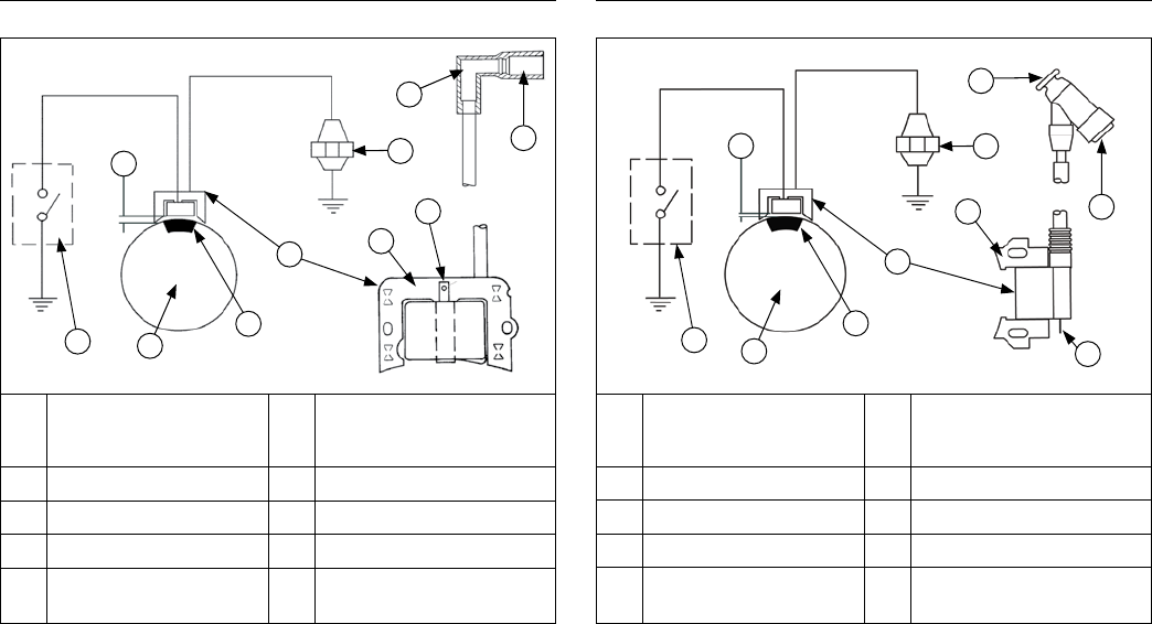
CDI Module Operation (aluminum ywheel)
Ignition System Components
A
B
C
D
G
H
I
E
F
J
A
Kill Switch/
Off Position of
Key Switch
B Flywheel
C Magnet D Ignition Module
E Lamination F Kill Terminal
G Spark Plug H Spark Plug Boot
I Spark Plug Terminal J
Air Gap
0.254 mm (0.010 in.)
As ywheel rotates and magnet passes CDI ignition
module, magnetic eld induces current in charging coil.
Current pulse is rectied by a diode and this signal
charges a high-voltage capacitor. As magnet completes
its pass, a change in polarity of signal produced by
ywheel magnet turns on semiconductor switch, and
directly connects charged capacitor to primary coil of
transformer. As capacitor discharges energy, low voltage
at primary winding is transformed to high voltage in
secondary winding of module. A high voltage pulse
is then delivered to spark plug, where it arcs across
electrode gap and ignites fuel in combustion chamber.
This system consists of following components:
● Magnets, permanently afxed to ywheel.
● Spark plug with rubber boot.
● Electronic, capacitive discharge ignition module
mounted on engine crankcase.
● Kill switch (or key switch); grounds module to stop
engine.
ELECTRONIC IGNITION SYSTEM
These engines are equipped with dependable solid-state magneto ignition systems. Two types of ignition modules are
used on these engines, capacitive discharge ignition (CDI), and inductive discharge ignition (IDI).
Both ignition systems are designed to be trouble free for life of engine. Other than periodically checking/replacing
spark plugs, no maintenance or timing adjustments are necessary or possible. Mechanical systems do occasionally
fail or break down. Refer to Troubleshooting to determine root of a reported problem.
Reported ignition problems are most often due to poor connections. Before beginning test procedure, check all
external wiring. Be certain all ignition-related wires are connected, including spark plug leads. Be certain all terminal
connections t snugly. Make sure ignition switch is in run position.
IDI Module Operation (cast iron ywheel)
Ignition System Components
A
B
C
D
G
H
I
E
F
J
A
Kill Switch/
Off Position of
Key Switch
B Flywheel
C Magnet D Ignition Module
E Lamination F Kill Terminal
G Spark Plug H Spark Plug Boot
I Spark Plug Terminal J
Air Gap
0.254 mm (0.010 in.)
As ywheel rotates and magnet passes IDI ignition
module, magnetic eld induces current in primary
coil. As ignition magnet completes its pass, it induces
current in a small triggering coil, which then turns on a
semiconductor switch. This causes previously induced
magnetic eld in primary coil to collapse. As magnetic
eld collapses, it causes voltage in secondary coil to
rise quickly. This sharp rise in voltage is sufcient to
arc across spark plug’s gap, and ignite fuel mixture in
combustion chamber. This system consists of following
components:
● Magnets, permanently afxed to ywheel.
● Spark plug with metal boot.
● Electronic, inductive discharge ignition module
mounted on engine crankcase.
● Kill switch (or key switch); grounds module to stop
engine.

30
Electrical System
KohlerEngines.com 14 690 01 Rev. G
Electronic Ignition Systems Tests
Test Ignition System
1. Make sure spark plug lead is connected to spark plug.
2. Check condition of spark plug. Make sure gap is set to 0.76 mm (0.030 in.).
Condition Possible Cause Conclusion
Spark plug is not receiving ignition
pulse.
Spark Plug Check gap and adjust if necessary;
reinstall plug.
Spark plug in bad condition. Spark Plug Replace plug, set gap, and install.
Test for Spark
NOTE: To maintain engine speeds obtained during cranking, do not remove spark plug.
Test for spark with ignition tester.
1. Disconnect spark plug lead and connect to post terminal of tester. Connect clip to ground, not to spark plug.
2. Turn engine ignition switch to START/RUN position to initiate test.
3. Crank engine to minimum of 500 RPM, and observe tester. Visible and audible sparks should be produced.
4. Release switch to RUN position. Visible and audible sparks should be produced.
Condition Possible Cause Conclusion
Visible and audible sparks are
produced.
Ignition Module Ignition module is OK.
Visible and audible sparks are not
produced.
Ignition Module or
Wiring and Connections
Make sure ignition switch, kill switch
or key switch is in RUN position.
Check all safety and operator
presence control switches (for
example: ywheel brake kill switch)
and other components, including
wiring and connections for accidental
grounding.
If components, wiring, including
terminals are all veried OK, test
ignition module.
Test Ignition Module
1. Disconnect kill lead from terminal on ignition module.
2. Pull retractable starter or crank engine to a minimum of 500 RPM and check for spark.
Condition Possible Cause Conclusion
Visible and audible sparks are
produced.
Ignition System or
Wiring and Connections
Problem is elsewhere in system/
wiring.
Visible and audible sparks are not
produced.
Ignition Module Replace ignition module.
31
Starter System
14 690 01 Rev. G KohlerEngines.com
NOTE: Do not crank engine continuously for more than
10 seconds. Allow a 60 second cool down period
between starting attempts. Failure to follow
these guidelines can burn out starter motor.
NOTE: If engine develops sufcient speed to disengage
starter but does not keep running (a false start),
engine rotation must be allowed to come to a
complete stop before attempting to restart
engine. If starter is engaged while ywheel is
rotating, starter pinion and ywheel ring gear
may clash and damage starter.
NOTE: If starter does not crank engine, shut off starter
immediately. Do not make further attempts to
start engine until condition is corrected.
NOTE: Do not drop starter or strike starter frame. Doing
so can damage starter.
Engines in this series use inertia drive electric starters or
retractable starters. Inertia drive electric starters are not
serviceable.
XT electric starters use brake switch for an interlock
(on ground). When bail is held down, switch in brake
assembly completes circuit of ground for starter. If there
is a no crank situation, cause could be brake assembly,
battery, key switch, wiring harness, fuse, or starter itself.
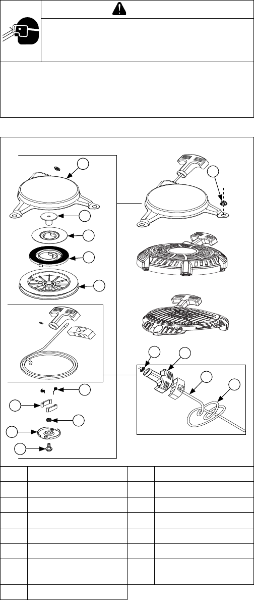
RETRACTABLE STARTERS
WARNING
Uncoiling Spring can cause severe injury.
Wear safety goggles or face protection when
servicing retractable starter.
Retractable starters contain a powerful, recoil spring
that is under tension. Always wear safety goggles
when servicing retractable starters and carefully follow
instructions in Retractable Starter for relieving spring
tension.
Retractable Starter Components
A
C
O
D
E
G
I
H
F
B
J
K
L
A Housing B Recoil Bushing
C Recoil Plate D Recoil Spring
E Pulley F Drive Pawl Springs
G Drive Pawl (Dogs) H Pulley Spring
I Drive Plate J Center Screw
K Grommet L Starter Handle
M Starter Rope N
Double Left-Hand
Knot
O Hex Flange Nut
M
N

32
Starter System
KohlerEngines.com 14 690 01 Rev. G
Remove Starter
NOTE: Whenever possible, an impact wrench should be
used to loosen nuts securing retractable starter.
1. Remove nuts securing starter to blower housing.
2. Remove starter assembly.
Rope Replacement
NOTE: Do not allow pulley/spring to unwind. Enlist aid
of a helper if necessary.
Rope can be replaced without complete starter
disassembly.
1. Remove starter assembly from engine.
2. Pull rope out approximately 12 in. and tie a
temporary (slip) knot in it to keep it from retracting
into starter.
3. Pull knot end out of handle, untie knot, and slide
handle off.
4. Hold pulley rmly and untie slipknot. Allow pulley to
rotate slowly as spring tension is released.
5. When all spring tension on starter pulley is released,
remove rope from pulley.
6. Tie a double left-hand knot in one end of new rope.
7. Rotate pulley counterclockwise to pre-tension spring
(approximately 4 full turns of pulley).
8. Continue rotating pulley counterclockwise until rope
hole in pulley is aligned with rope guide bushing of
starter housing.
9. Insert unknotted end of new rope through rope hole
in starter pulley and rope guide bushing of housing.
10. Tie a slipknot approximately 12 in. from free end of
rope. Hold pulley rmly and allow it to rotate slowly
until slipknot reaches guide bushing of housing.
11. Insert starter rope through starter handle and tie a
double, left-hand knot at end of starter rope. Insert
knot into hole in handle.
12. Untie slip knot and pull on starter handle until starter
rope is fully extended. Slowly retract starter rope into
starter assembly. If recoil spring is properly
tensioned, starter rope will retract fully and starter
handle will stop against starter housing.
Pawls (dogs) Replacement
1. Install a clamp to hold pulley in starter housing and
prevent it from rotating.
2. Unscrew center screw and lift off drive plate.
3. Note positions of pawls and pawl springs before
removing. Remove parts from pulley.
4. Install pawl springs and pawls into pawl slots of
pulley. All parts must by dry.
5. Position drive plate over pawls, aligning actuating
slots in place with raised sections on each drive
pawl. Torque center screw to 5-6 N·m (44-54 in. lb.).
6. Remove clamp and pull starter rope out part way to
check operation of pawls.
Install Starter
1. Place starter onto studs protruding from blower
housing. Start nuts onto studs, but do not tighten.
2. Pull starter handle out until pawls engage in drive
cup. Hold handle in this position and torque nuts to 8
N·m (71 in. lb.).
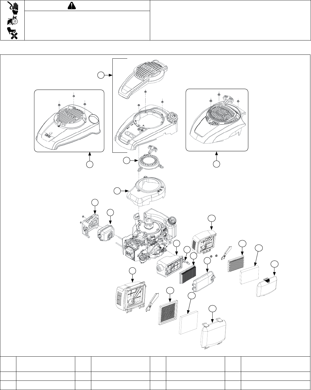
33
Disassembly/Inspection and Service
14 690 01 Rev. G KohlerEngines.com
WARNING
Before working on engine or equipment, disable engine as
follows: 1) Disconnect spark plug lead(s). 2) Disconnect
negative (–) battery cable from battery.
Accidental Starts can cause severe injury or
death.
Disconnect and ground spark plug lead(s)
before servicing.
External Engine Components
F
G
E
D
A
K
C
B
J
H
I
K
J
H
L
H
J
L
K
A
Engine Cover and
Insert
B Engine Cover C
Engine Cover and
Retractable Start
D Retractable Starter
E Blower Housing F Mufer Guard G Mufer H Air Cleaner Base
I Breather Hose J Paper Element K Air Cleaner Cover L Precleaner
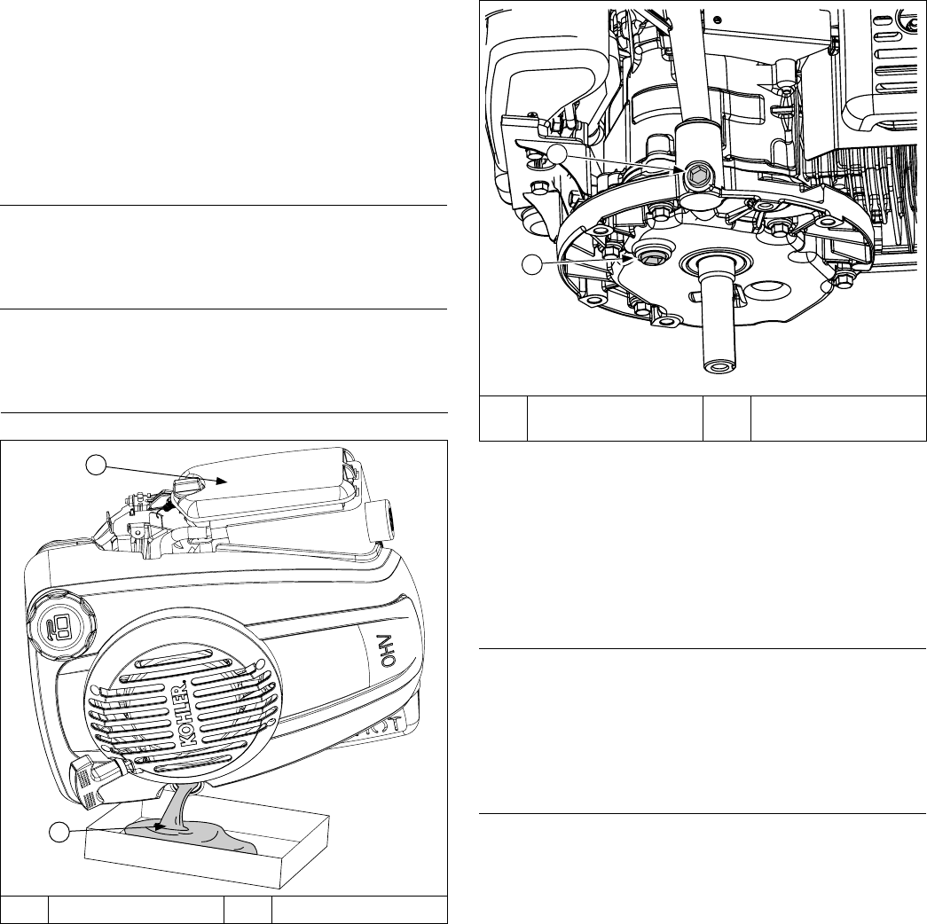
34
Disassembly/Inspection and Service
KohlerEngines.com 14 690 01 Rev. G
Drain Oil From Crankcase Plug (if accessible)
B
A
A Crankcase Plug B
Crankcase Plug
(Bottom of Engine)
1. To keep dirt, grass clippings, and other debris out of
engine, clean area around oil ll cap/dipstick, and
then remove it.
2. Remove crankcase plug on bottom of engine.
3. Drain oil into an approved container.
4. Dispose of used oil in accordance with local
ordinances.
Remove Engine Cover Insert (if equipped) and
Cover
NOTE: Whenever possible, an impact wrench should be
used to loosen nuts securing retractable starter.
1. Remove Torx screws securing engine cover insert.
2. Remove nuts securing engine cover. Remove
engine cover.
Remove Engine Cover and Retractable Starter (if
equipped)
NOTE: Whenever possible, an impact wrench should be
used to loosen nuts securing retractable starter.
Remove nuts securing engine cover and retractable
starter. Remove engine cover and retractable starter.
Clean all parts thoroughly as engine is disassembled.
Only clean parts can be accurately inspected
and gauged for wear or damage. There are many
commercially available cleaners that will quickly remove
grease, oil, and grime from engine parts. When such a
cleaner is used, follow manufacturer's instructions and
safety precautions carefully.
Make sure all traces of cleaner are removed before
engine is reassembled and placed into operation. Even
small amounts of these cleaners can quickly break down
lubricating properties of engine oil.
Disconnect Spark Plug
NOTE: Pull on boot only, to prevent damage to spark
plug lead.
Disconnect lead from spark plug.
Empty Fuel Tank
1. Ensure fuel tank is empty by running engine until it
stops, and is completely out of fuel.
2. Remove gas cap.
Drain Oil From Crankcase
Drain Oil from Dipstick Tube
B
A
A Air Cleaner B Oil
1. To keep dirt, grass clippings, and other debris out of
engine, clean area around oil ll cap/dipstick.
2. Remove oil ll cap/dipstick.
3. Tilt engine on its side with air cleaner facing up.
Drain oil into an approved container.
4. After crankcase is completely drained, tilt engine
back to level.
5. Dispose of used oil in accordance with local
ordinances.
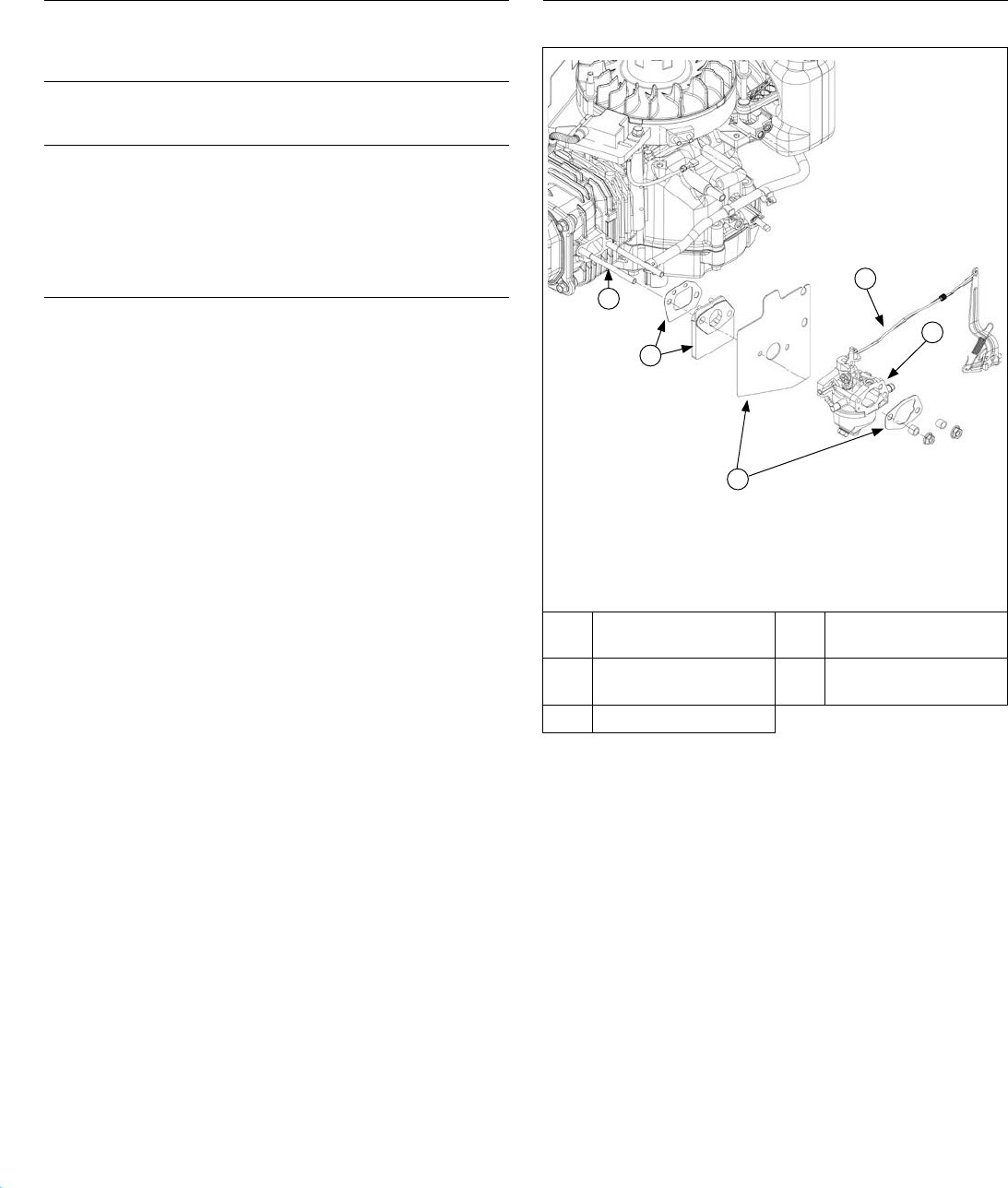
35
Disassembly/Inspection and Service
14 690 01 Rev. G KohlerEngines.com
Remove Retractable Starter
Remove screws securing retractable starter assembly to
engine.
Remove Blower Housing
Lift off blower housing and retain stud spacers.
Remove Mufer Assembly
1. Remove nuts securing mufer guard to cylinder
head.
2. Slide mufer off studs.
3. Remove heat deector gasket from exhaust studs,
noting orientation.
Remove Air Cleaner Assembly
1. Loosen knob or unhook latch and remove air cleaner
cover.
2. Remove paper element and foam precleaner (if
equipped).
3. Remove nuts and screw securing air cleaner base to
cylinder head and crankcase.
4. Detach breather hose from crankcase.
5. Remove air cleaner base and detach primer hose
from carburetor (primer bulb equipped models only).
6. Remove air cleaner base gasket from carburetor,
noting orientation.
Carburetor Components
Remove Carburetor with Primer or Carburetor with
Choke (if equipped)
D
E
B
A
C
A Carburetor Stud(s) B
Gasket and Spacer
Kit
C
Gasket and Heat
Shield Kit
D Linkage
E Carburetor
NOTE: Ensure fuel tank is empty by running engine until
it stops, and is completely out of fuel.
1. Squeeze hose clamp and slide it and fuel line off
carburetor.
2. Slide carburetor to end of intake studs.
3. Turn throttle lever clockwise until it stops. Gently
push rod and spring linkages up to disconnect them
from throttle lever.
4. Rotate carburetor until choke linkage can be
disconnected from carburetor. If equipped.
5. Slide off carburetor heat shield, spacer, and gasket,
noting sequence.
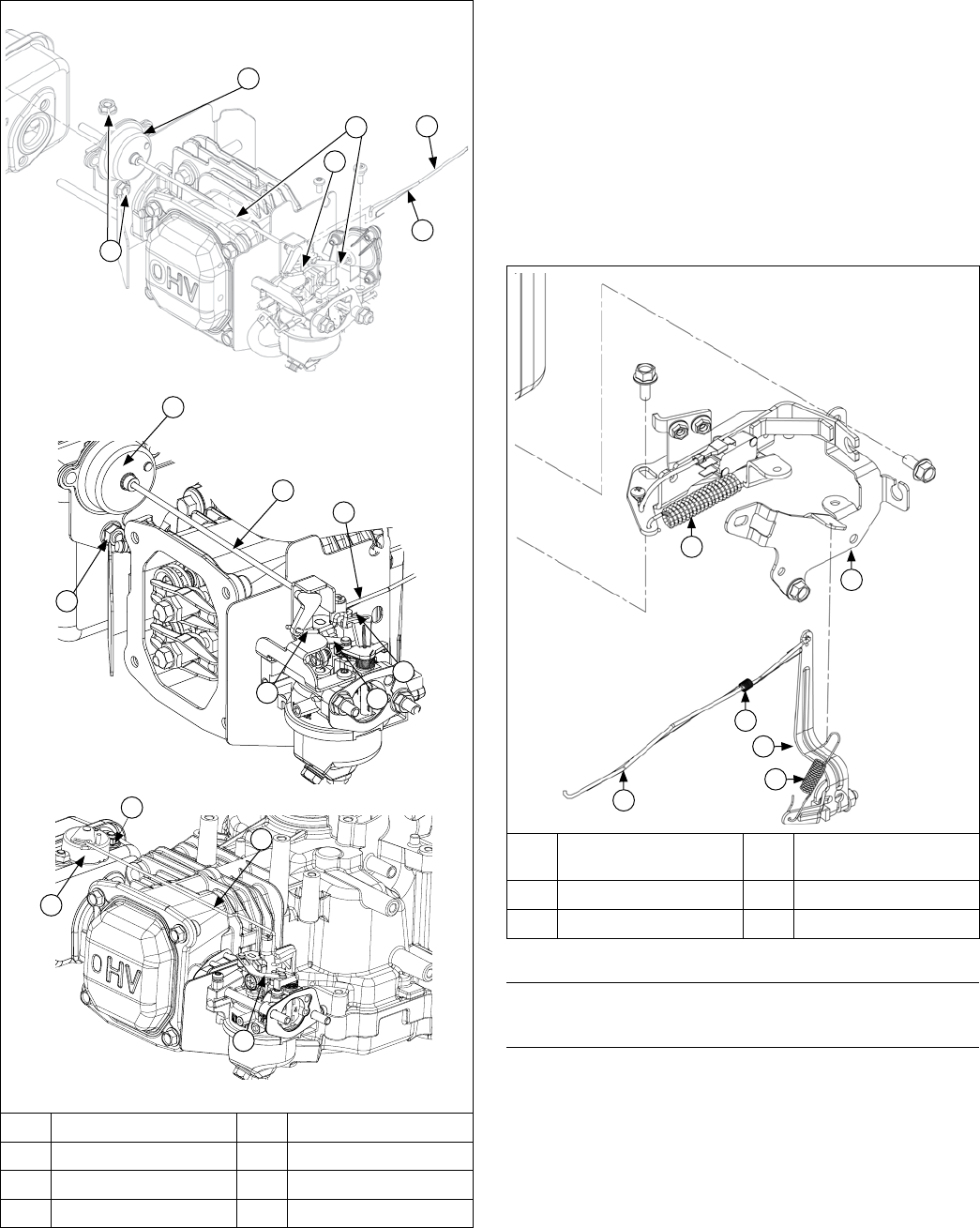
36
Disassembly/Inspection and Service
KohlerEngines.com 14 690 01 Rev. G
Remove Carburetor with Auto Choke (if equipped)
B
C
A
F
E
D
G
E
F
A
H
B
C
A Nut(s) B Arm Assembly
C Linkage D Choke Linkage
E Governor Linkage F Linkage Spring
G Wire Choke Linkage H Choke Link
1. Remove screws securing arm assembly to
carburetor.
2. Disconnect fuel line.
3. Remove wire choke linkage while sliding carburetor
away from engine a couple of inches.
4. Disconnect governor linkage and linkage spring from
carburetor.
5. Remove carburetor.
6. Remove nuts securing arm assembly to mufer.
Second nut is located behind arm assembly base
securing it to top of mufer.
7. Remove arm assembly from mufer.
Control Components
D
E
F
C
B
A
A Flywheel Brake
Spring
B Speed Control
Bracket
C Linkage Spring D Governor Lever
E Governor Spring F Throttle Linkage
Remove Speed Control Bracket
Disconnect governor spring from speed control bracket.
Remove Speed Control Bracket
NOTE:
Fuel hose connecting carburetor and fuel tank is
held in place by a plastic ring, mounted on back of
speed control bracket. If bracket is removed from
crankcase, it will remain attached to fuel hose (not
including California engines). Should replacement
of speed bracket be required, disconnect fuel line
from fuel lter or carburetor and slide bracket off
hose. Do not disconnect fuel hose from fuel tank.
Remove screws securing speed control bracket.
B
A
C
H
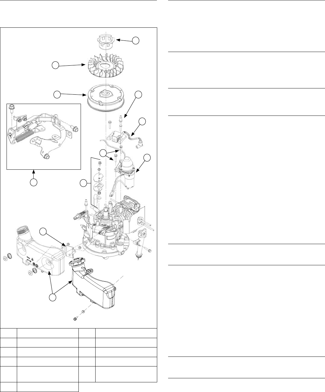
37
Disassembly/Inspection and Service
14 690 01 Rev. G KohlerEngines.com
Remove Governor Lever
Loosen governor lever nut and slide lever off governor
shaft.
Flywheel/Ignition/Fuel Tank Components
F
G
H
D
K
B
A
J
E
C
I
A Fuel Tank B Crankcase Bracket
C Electric Starter D Ignition Module
E Stud(s) F Drive Cup
G Fan H Flywheel
I Screw(s) J
Flywheel Brake
Assembly
K Breather Assembly
Remove Fuel Tank
1. Ensure fuel tank is empty.
2. Detach fuel tank from crankcase bracket by
removing nut or screw.
3. Remove studs securing top of fuel tank and lift off
tank.
Remove Ignition Module
1. Disconnect kill lead from ignition module.
2. Remove screw and stud securing ignition module.
Mark stud for identication during reassembly.
Disconnect Flywheel Brake Spring
Grasp 1 end of ywheel brake spring with a pliers and
stretch it to disconnect it.
Remove Flywheel
1. Using a ywheel strap wrench to hold ywheel,
remove nut inside drive cup.
2. Remove drive cup and lift off fan, noting orientation
on ywheel for reassembly.
3. Flywheel is mounted on a tapered shaft. To break it
loose, use a rubber mallet to land a rm blow toward
outer rim of ywheel. Remove ywheel.
4. Remove ywheel key from crankshaft.
Inspection
Inspect ywheel for cracks and check keyway for wear
or damage. Replace ywheel if cracked. If ywheel key
is sheared or keyway is damaged, replace crankshaft,
ywheel, and key.
Inspect ring gear for cracks or damage. Ring gears are
not available separately. Replace ywheel if ring gear is
damaged.
Remove Electric Starter (if equipped)
Remove screws securing electric starter to engine.
Remove Breather Assembly
Breather system is designed to control amount of oil
in head area and still maintain necessary vacuum in
crankcase.
When pistons move downward, crankcase gases are
pushed past reed through mesh lter into intake system.
Upward travel of pistons closes reed and creates a
low vacuum in lower crankcase. Any oil separated out
through lter drains back into crankcase.
1. Remove screws securing breather cover. Remove
cover.
2. Remove breather spring, disc and screen.
Remove Spark Plug
Remove spark plug from cylinder head.
Remove Flywheel Brake Assembly
Remove screws securing ywheel brake assembly;
retain spacers (if equipped).
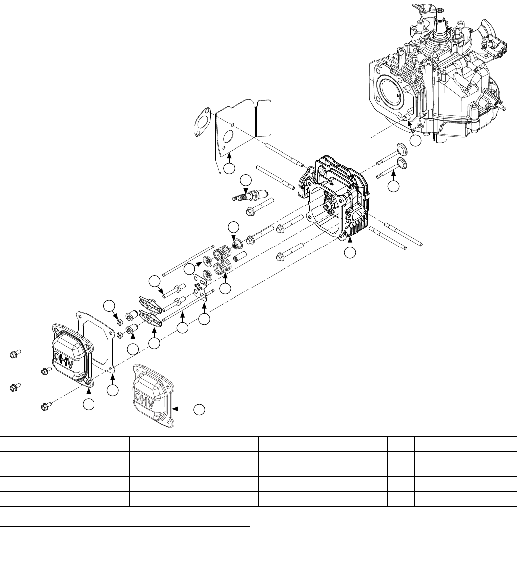
38
Disassembly/Inspection and Service
KohlerEngines.com 14 690 01 Rev. G
Cylinder Head Components
A
B
D
E
G
H
I
J
M
O
N
P
K
L
F
C
A Valve Cover B Gasket C Jam Nut D Rocker Arm Pivot
E Rocker Arms F Rocker Arm Stud G Push Rod H Push Rod Guide
Plate
I Valve Keeper J Valve Spring K Intake Valve Seal L Spark Plug
M Bafe N Cylinder Head O Valve P Dowel Pin
Remove Valve Cover
Valve Cover with Gasket
1. Remove screws from valve cover.
2. Remove cover and gasket.
Valve Cover with RTV Sealant
NOTE:
Valve cover is sealed to cylinder head using RTV
silicone sealant. When removing valve cover, use
care not to damage gasket surfaces of cover and
cylinder head. To break RTV seal, hold a block of
wood against 1 at face of valve cover. Strike wood
rmly with a mallet. If seal doesn't break loose after
1 or 2 attempts, repeat procedure on other side.
1. Remove screws securing valve cover.
2. Using a brass wire brush and gasket remover or
similar solvent, clean old RTV from surface of
cylinder head and valve cover.
Remove Jam Nuts and Rocker Arm Pivots
Use a socket and wrench to remove jam nuts and rocker
arm pivots from rocker studs.
A
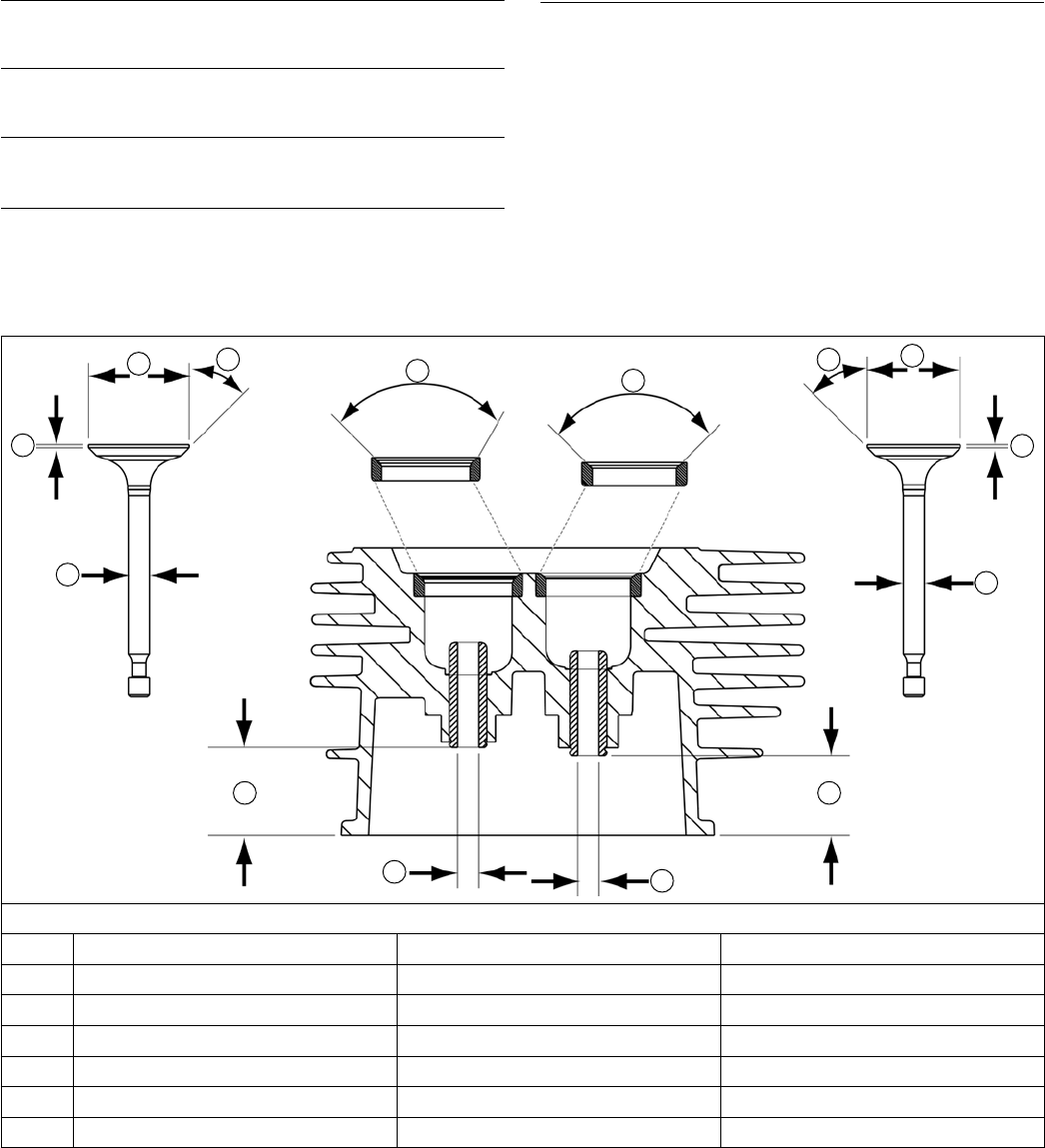
39
Disassembly/Inspection and Service
14 690 01 Rev. G KohlerEngines.com
Valve Details
F
D
G
E
A
A
E
D
F
G
BB
C
C
Dimension Intake Exhaust
A Seat Angle
90° 90°
B Guide Depth 22.6 mm 20.5 mm
C Guide I.D. 5.500/5.512 mm 5.500/5.512 mm
D Valve Head Diameter 25.875/26.125 mm 23.875/24.125 mm
E Valve Face Angle
45° 45°
F Valve Margin (Min.) 0.80 mm 0.80 mm
G Valve Stem Diameter 5.465/5.480 mm 5.465/5.480 mm
Remove Rocker Arms
Noting orientation, lift rocker arms off rocker studs.
Remove Push Rods
Remove push rods and mark them for reinstallation.
Remove Rocker Studs
Unscrew and remove rocker studs from cylinder head.
Remove Guide Plate
1. Remove guide plate from rocker studs.
2. Note orientation of guide plate (tabs down) for use
during reassembly.
Remove Cylinder Head
1. Remove screws securing cylinder head.
2. Remove cylinder head, noting positioning of dowels.
3. Remove head gasket and discard.
Valve Inspection and Service
Carefully inspect valve mechanism parts. Inspect valve
springs and related hardware for excessive wear or
distortion. Check valves and valve seats for evidence
of deep pitting, cracks, or distortion. Following diagram
outlines valve running clearances between valve stems
and guides.

40
Disassembly/Inspection and Service
KohlerEngines.com 14 690 01 Rev. G
Remove Valve Assembly
NOTE: Only intake valve has a seal. There is no valve
seal on exhaust side.
1. Push down on valve spring keepers to release valve
springs from valve stems.
2. Remove valve spring keepers and springs.
3. Push end of intake valve to release valve seal.
4. Remove both valves from opposite side of head.
Inspection and Service
Hard starting, or loss of power accompanied by high fuel
consumption, may be symptoms of faulty valves.
Although these symptoms could also be attributed to
worn rings, remove and check valves rst. After removal,
clean valve heads, faces, and stems with a power wire
brush. Then, carefully inspect each valve for defects
such as warped head, excessive corrosion, or worn stem
end. Replace valves found to be in bad condition.
Valve Guides
To check valve guide-to-valve stem clearance,
thoroughly clean valve guide and, using a split-ball
gauge, measure inside diameter. Then, using an outside
micrometer, measure diameter of valve stem at several
points on stem where it moves in valve guide. Use
largest stem diameter to calculate clearance. If intake
clearance exceeds 0.047 mm (.0018 in.) or exhaust
clearance exceeds 0.082 mm (.0032 in.), determine
whether valve stem or guide is responsible for excessive
clearance.
Maximum (I.D.) wear on intake valve guide is 5.512 mm
(0.2170 in.), while 5.512 mm (0.2170 in.) is maximum
allowed on exhaust guide. Guides are not removable. If
guides are within limits but valve stems are worn beyond
limits, replace valves.
Valve Seat Inserts
Hardened steel alloy intake and exhaust valve seat
inserts are press tted into cylinder head. Inserts are
not replaceable, but they can be reconditioned if not too
badly pitted or distorted. If seats are cracked or badly
warped, cylinder head should be replaced.
Recondition valve seat inserts following instructions
provided with valve seat cutter (A) being used. Final cut
should be made with an 90° cutter as specied for valve
seat angle. With proper 45° valve face angle, and valve
seat cut properly (44.5° as measured from center line
when cut 90°) this would result in desired 0.5° (1.0° full
cut) interference angle where maximum pressure occurs
on valve face and seat.
Lapping Valves
Reground or new valves must be lapped in, to provide
a good seal. Use a hand valve grinder with suction
cup for nal lapping. Lightly coat valve face with ne
grade of grinding compound, then rotate valve on seat
with grinder. Continue grinding until smooth surface is
obtained on seat and on valve face. Thoroughly clean
cylinder head in soap and hot water to remove all traces
of grinding compound. After drying cylinder head, apply
a light coating of engine oil to prevent rusting.
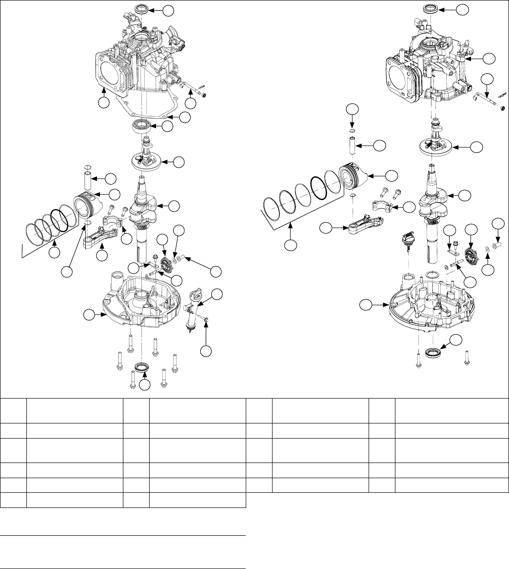
41
Disassembly/Inspection and Service
14 690 01 Rev. G KohlerEngines.com
Crankcase Components
T
R
O
N
Q
P
K
L
B
C
M
S
F
H
I
G
E
D
A
J
V
U
A Crankcase Oil Seal B Crankcase C
Governor Cross
Shaft
D Oil Pan Gasket
E Crankcase Bearing F Camshaft G Piston Pin Retainer H Piston Pin
I Piston J Piston Ring Set K Connecting Rod L
Connecting Rod
End Cap
M Crankshaft N Retainer O Governor Shaft P Governor Gear
Q Governor Washer R Governor Cup S Oil Pan T Oil Pan Oil Seal
U Dipstick Tube V Screw
Remove Dipstick Tube (Extended Dipstick)
Remove screw securing dipstick tube. Remove tube.
Remove Oil Pan
NOTE: Some engines have an oil pan gasket; some
engines use RTV to secure oil pan to crankcase.
1. Remove screws securing oil pan.
2. Using a at blade screwdriver as a wedge, carefully
separate oil pan from crankcase.
3. Remove old gasket (if equipped) and discard.
Inspection
Inspect oil seal in oil pan and remove it if it is worn or
damaged.
A
B
C
G
F
H
I
J
K
L
M
O
R
P
Q
S
T
N

42
Disassembly/Inspection and Service
KohlerEngines.com 14 690 01 Rev. G
Remove Camshaft
Remove camshaft from crankcase.
Inspection and Service
Inspect gear teeth of camshaft. If teeth are badly worn
or chipped, or if some are missing, replacement of
camshaft will be necessary. If unusual wear or damage
is evident on either camshaft lobes or mating tappets
camshaft and both tappets must be replaced. Check
condition and operation of Automatic Compression
Release (ACR) mechanism.
ACR
These engines are equipped with an ACR mechanism.
ACR lowers compression at cranking speeds to make
starting easier.
ACR mechanism consists of a decompression weight
and arm mounted to camshaft, and activated by a return
spring. When engine is rotating at low cranking speeds
(1000 RPM or less), decompression weight holds arm
so it protrudes above heel of exhaust lobe. This holds
exhaust valve off its seat during rst part of compression
stroke.
After engine speed increases above approximately 1000
RPM, centrifugal force causes decompression weight
to move outward, causing arm to retract. When in this
position, arm has no effect on exhaust valve and engine
operates at FULL compression and power.
Benets
As a result of reduced compression at cranking speeds,
several important benets are obtained:
1. Manual (retractable) starting is much easier. Without
ACR, manual starting would be virtually impossible.
2. Electric start models can use a smaller starter and
battery which are more practical for application.
3. ACR eliminates need for a spark retard/advance
mechanism. A spark retard/advance mechanism
would be required on engines without ACR to
prevent kickback which would occur during starting.
ACR eliminates this kickback, making manual
starting safer.
4. Choke control setting is less critical with ACR. If
ooding occurs, excess fuel is blown out opened
exhaust valve and does not hamper starting.
5. Engines with ACR start much faster in cold weather
than engines without ACR.
6. Engines with ACR can be started with spark plugs
which are worn or fouled. Engines without ACR are
more difcult to start with those same spark plugs.
Remove Governor Gear and Shaft
1. Remove screw and retainer securing governor gear.
2. Remove hitch pin securing governor shaft. Remove
shaft.
Inspection
Inspect governor gear teeth. Replace gear if it is worn,
chipped, or if any teeth are missing. Inspect governor
weights. They should move freely in governor gear.
Remove Tappets
Remove tappets. Mark them INTAKE and EXHAUST for
reinstallation.
Remove Connecting Rod Cap
Rotate crankshaft to allow access to 2 screws on
connecting rod cap. Remove screws and cap.
Remove Piston and Connecting Rod
Carefully guide piston and attached connecting rod out
of cylinder bore.
Connecting Rod Inspection and Service
Check bearing area (big end) for excessive wear, score
marks, running and side clearances. Replace connecting
rod and end cap if scored or excessively worn.
Service replacement connecting rods are available in
STD size.
Piston and Rings Inspection
Scufng and scoring of pistons and cylinder walls occurs
when internal engine temperatures approach welding
point of piston. Temperatures high enough to do this are
created by friction, which is usually attributed to improper
lubrication and/or overheating of engine.
Normally, very little wear takes place in piston boss or
piston pin area. If original piston and connecting rod can
be reused after new rings are installed, original pin can
also be reused but new piston pin retainers are required.
Piston pin is included as part of piston assembly – if pin
boss in piston or pin itself is worn or damaged, a new
piston assembly is required.
Ring failure is usually indicated by excessive oil
consumption and blue exhaust smoke. When rings fail,
oil is allowed to enter combustion chamber where it is
burned along with fuel. High oil consumption can also
occur when piston ring end gap is incorrect, because
ring cannot properly conform to cylinder wall under this
condition. Oil control is also lost when ring gaps are not
staggered during installation.
When cylinder temperatures get too high, lacquer and
varnish collect on pistons, causing rings to stick, which
results in rapid wear. A worn ring usually takes on a
shiny or bright appearance.
Scratches on rings and pistons are caused by abrasive
material such as carbon, dirt, or pieces of hard metal.
Detonation damage occurs when a portion of fuel charge
ignites spontaneously from heat and pressure shortly
after ignition. This creates two ame fronts, which meet
and explode to create extreme hammering pressures on
a specic area of piston. Detonation generally occurs
from using low octane fuels.
Preignition or ignition of fuel charge before timed spark
can cause damage similar to detonation. Preignition
damage is often more severe than detonation damage.
Preignition is caused by a hot spot in combustion
chamber such as glowing carbon deposits, blocked
cooling ns, an improperly seated valve, or a wrong
spark plug.
Replacement pistons are available in STD bore size.
Replacement pistons include new piston ring sets and
new piston pins.
Replacement ring sets are also available separately
for STD pistons. Always use new piston rings when
installing pistons. Never use old rings.
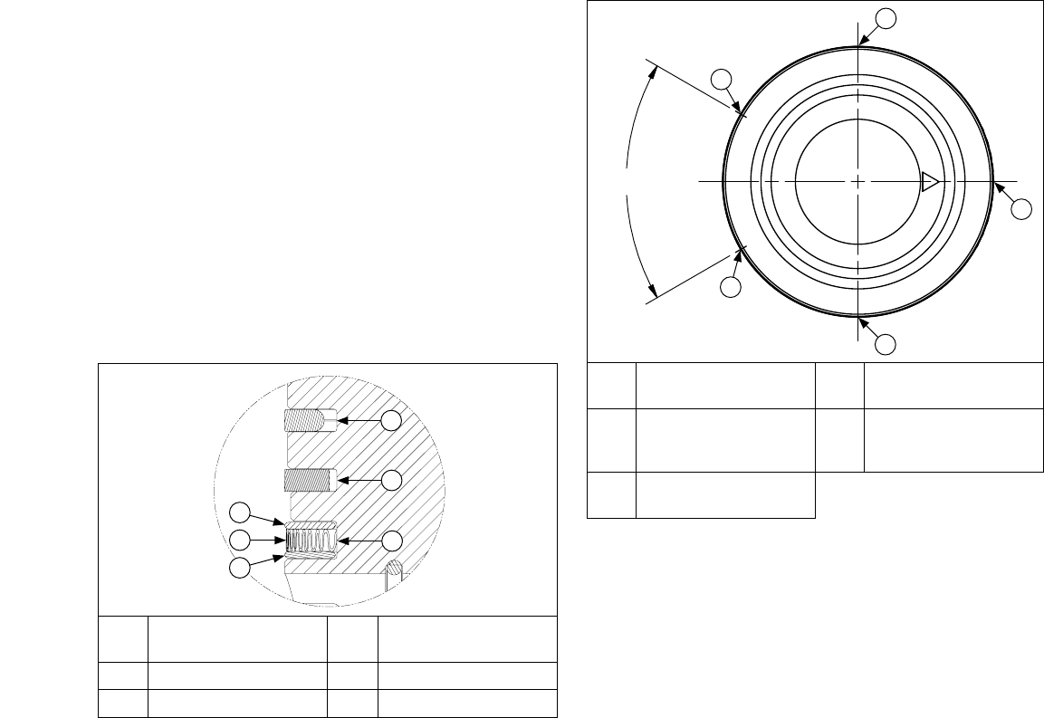
43
Disassembly/Inspection and Service
14 690 01 Rev. G KohlerEngines.com
Some important points to remember when servicing
piston rings:
1. Cylinder bore must be de-glazed before service ring
sets are used.
2. If cylinder bore does not need re-boring and if old
piston is within wear limits and free of score or scuff
marks, old piston may be reused.
3. Remove old rings and clean up grooves. Never
reuse old rings.
4. Before installing new rings on piston, place top 2
rings, each in turn, in its running area in cylinder
bore and check end gap. Compare ring gap to
Clearance Specications.
5. After installing new compression (top and middle)
rings on piston, check piston-to-ring side clearance.
Compare clearance to Clearance Specications. If
side clearance is greater than specied, a new
piston must be used.
Install New Piston Rings
C
D
E
F
B
A
A
Top Compression
Ring
B
Middle Compression
Ring
C Oil Control Ring D Top Rail
E Expander Ring F Bottom Rail
Piston Ring Orientation
A
B
C
D
E
(≥ 60°)
A
Oil Ring Expander
Gap
B Bottom Oil Rail Gap
C Top Oil Rail Gap D
Intermediate
Compression
Ring Gap
E
Top Compression
Ring Gap
NOTE: Rings must be installed correctly. Install oil
control ring assembly (bottom groove) rst,
middle compression ring (center groove)
second, and top compression ring (top groove)
last. Oil control ring assembly is a three-piece
design, and consists of a top rail, expander ring,
and bottom rail.
Use a piston ring expander to install rings.
1. Oil control ring assembly (bottom groove): Install
expander rst then bottom rail and top rail last. Make
sure ends of expander are not overlapped. Adjust
ring gaps.
2. Middle compression ring (center groove): Install
middle compression ring using a piston ring
expander tool. Make sure identication mark is up or
colored dye stripe (if contained) is left of end gap.
Adjust ring gaps.
3. Top compression ring (top groove): Install top
compression ring using a piston ring expander tool.
Make sure identication mark is up or colored dye
stripe (if contained) is left of end gap. Adjust ring
gaps.

44
Disassembly/Inspection and Service
KohlerEngines.com 14 690 01 Rev. G
Remove Crankshaft
Remove crankshaft.
Inspection and Service
Inspect gear teeth of crankshaft and ACR gear. If any
teeth are badly worn or chipped, or if some are missing,
replacement of crankshaft will be necessary.
Inspect crankshaft bearing surfaces for scoring,
grooving, etc. Measure running clearance between
crankshaft journals and their respective bearing bores.
Use an inside micrometer or telescoping gauge to
measure inside diameter of both bearing bores in vertical
and horizontal planes. Use an outside micrometer to
measure outside diameter of crankshaft main bearing
journals. Subtract journal diameters from their respective
bore diameters to get running clearances. Check results
against values in Specications and Tolerances. If
running clearances are within specication, and there
is no evidence of scoring, grooving, etc., no further
reconditioning is necessary. If bearing surfaces are worn
or damaged, crankcase and/or closure plate will need to
be replaced.
Inspect crankshaft keyway. If worn or chipped,
replacement of crankshaft will be necessary.
Inspect crankpin for score marks or metallic pickup.
Slight score marks can be cleaned with crocus cloth
soaked in oil. If wear limits in Specications are
exceeded, it will be necessary to replace crankshaft.
Crankcase
Inspection and Service
Check all gasket surfaces to make sure they are free of
gasket fragments and deep scratches or nicks.
Check cylinder wall for scoring. In severe cases,
unburned fuel can dissolve lubricating oil off piston and
cylinder wall. Without lubrication, piston rings would
make metal to metal contact with wall, causing scufng
and scoring. Scoring of cylinder wall can also be caused
by localized hot spots from blocked cooling ns or from
inadequate or contaminated lubrication.
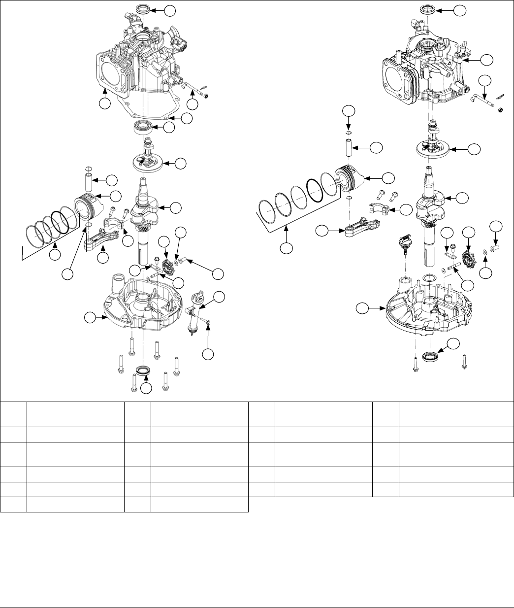
45
Reassembly
14 690 01 Rev. G KohlerEngines.com
Crankcase Components
T
R
O
N
Q
P
K
L
B
C
M
S
F
H
I
G
E
D
A
J
V
U
A Crankcase Oil Seal B Crankcase C
Governor Cross
Shaft
D Oil Pan Gasket
E Crankcase Bearing F Camshaft G Piston Pin Retainer H Piston Pin
I Piston J Piston Ring Set K Connecting Rod L
Connecting Rod
End Cap
M Crankshaft N Retainer O Governor Shaft P Governor Gear
Q Governor Washer R Governor Cup S Oil Pan T Oil Pan Oil Seal
U Dipstick Tube V Screw
NOTE: Make sure engine is assembled using all specied torque values, tightening sequences, and clearances.
Failure to observe specications could cause severe engine wear or damage.
NOTE: Always use new gaskets.
NOTE: Make sure all components have been properly cleaned BEFORE reassembly.
NOTE: Remove all traces of cleaners before engine is reassembled and placed into operation. Even small amounts
of these cleaners can quickly break down lubricating properties of engine oil.
Install Crankshaft
Carefully install crankshaft into crankcase through front seal, and fully seat into place. Rotate crankshaft until journal
for connecting rod is away from cylinder.
A
B
C
G
F
H
I
J
K
L
M
O
R
P
Q
S
T
N

46
Reassembly
KohlerEngines.com 14 690 01 Rev. G
Install Oil Pan
Torque Sequence
XT-7, XTR-7, XT775, XT8
1
6
4
5
3
2
XT-6, XTR-6, XT6.5, XT6.75, XT650, XT675
1
6
4
5
7
3
2
Install Piston and Connecting Rod
NOTE: Proper orientation of piston and connecting rod
inside engine is extremely important. Improper
orientation can cause extensive wear or
damage.
1. Stagger piston rings in grooves until end gaps are
60° or more apart. Lubricate cylinder bore,
crankshaft journal, connecting rod journal, piston,
and rings with engine oil.
2. Compress piston rings using a piston ring
compressor.
3. Position triangle on top of piston toward push rod
chamber.
4. Carefully guide connecting rod, with piston attached,
into bore.
5. Use handle of a soft, rubber-grip hammer to tap
piston into bore.
6. Rotate crankshaft to mate with connecting rod. Align
rod cap and connecting rod to match marks. Torque
screws to 12.5 N·m (110 in. lb.).
Install Tappets
Install intake and exhaust tappets into their respective
positions, as previously marked.
Install Camshaft
1. Lubricate camshaft and cam gear surfaces with light
grease or oil.
2. Install camshaft and align timing marks.
Install Governor Gear Assembly
NOTE: When installing governor, at of governor shaft
(located on outside of crankcase) should be
turned so at is parallel to crankcase gasket
surface. Paddle of governor shaft (located inside
crankcase) should be pointing away from
crankcase gasket surface.
1. Install governor gear and retainer, and torque screw
to 9.5 N·m (84 in. lb.).
2. Install governor cross shaft and secure it with hitch
pin.
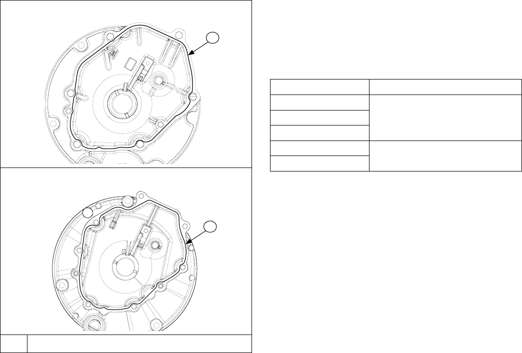
47
Reassembly
14 690 01 Rev. G KohlerEngines.com
NOTE: When installing oil pan, ensure plunger on
governor gear is pressed fully into governor.
Incorrectly installing governor plunger may result
in damage.
NOTE: Some engines use an oil pan gasket; some
engines use RTV to secure oil pan to crankcase.
1. Sealing surfaces of crankcase and oil pan should be
clean, dry and free of any nicks or burrs.
2. Install 2 crankcase dowels into crankcase.
3. OIL PAN GASKET: Using crankcase dowels as a
guide, install a new oil pan gasket onto crankcase.
RTV: Refer to Tools and Aids for a listing of
approved sealants. Always use fresh sealant. Using
outdated sealant can result in leakage. Using
sealant pattern, apply a 1.5 mm (1/16 in.) bead of
sealant to sealing surface of oil pan.
4. Guide oil pan onto crankcase, ensuring camshaft
and governor gear align with their mating surfaces.
Rotate crankshaft slightly to help engage governor
gear.
5. Install and nger tighten screws, securing oil pan to
crankcase.
6. Use torque sequence shown and torque oil pan
screws to:
Model Torque
XT6, XTR-6
11.0 N·m (98 in. lb.)XT6.5, XT6.75
XT650, XT675
XT-7, XTR-7
14.7 N·m (130 in. lb.)
XT775, XT8
Sealant Pattern
XT775, XT8
XT6.5, XT6.75
A 1.5 mm (1/16 in.) bead of sealant.
A
A
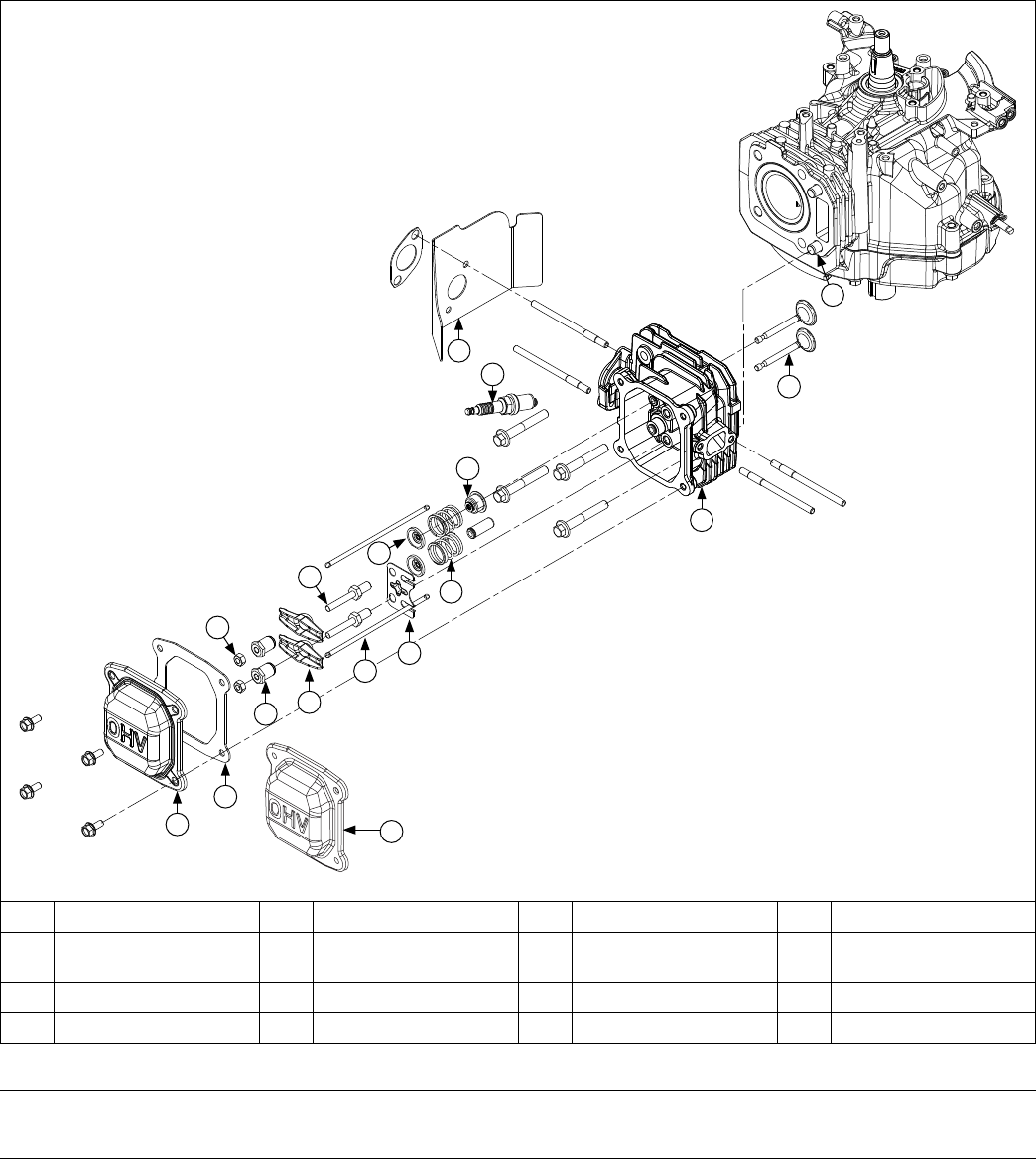
48
Reassembly
KohlerEngines.com 14 690 01 Rev. G
Cylinder Head Components
A
B
D
E
G
H
I
J
M
O
N
P
K
L
F
C
A Valve Cover B Gasket C Jam Nuts D Rocker Arm Pivot
E Rocker Arms F Rocker Arm Stud G Push Rods H
Push Rod Guide
Plate
I Valve Keeper J Valve Spring K Intake Valve Seal L Spark Plug
M Bafe N Cylinder Head O Valve P Dowel Pin
Install Cylinder Head Assembly
Prior to assembly, lubricate all components with engine oil, including tips of valve stems and valve guides.
Install Valve Train
1. Install intake and exhaust valves into their respective positions in cylinder head.
2. Install intake valve seal onto intake valve. Next, slide valve springs onto both valves and lock them in place with
valve spring keepers.
A
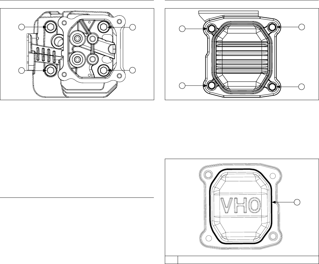
49
Reassembly
14 690 01 Rev. G KohlerEngines.com
Install Cylinder Head
Torque Sequence
2
4
1
3
NOTE: Do not reuse cylinder head gasket. Always
replace with new gasket.
1. Examine sealing surfaces of cylinder head and
crankcase for nicks or burrs.
2. Using cylinder head dowels as a guide, install a new
head gasket.
3. Match sides of head together and nger tighten
screws.
4. Torque screws in two stages; rst to 14 N·m
(123 in. lb.), nally to 27.8 N·m (246 in. lb.), following
sequence shown.
Install Push Rod Assembly
NOTE: Installation and seating of push rods into tappet
recesses during this sequence is critical. To aid
with proper installation of push rods and rocker
arms, and for adjusting valve lash, position
engine with cylinder head up. When properly
installed, push rods extend approximately 1 in.
(25.4 mm) above guide plate.
1. With tabs on guide plate facing down, install rocker
studs.
2. Tighten rocker studs to 13.6 N·m (120 in. lb.).
3. Install push rods into intake and exhaust positions,
as previously marked.
4. Apply grease to contact surfaces of rocker arms and
pivots.
5. Install rocker arms onto rocker studs. Match rocker
arm dimples with round push rod ends.
6. Loosely install pivots and jam nuts onto rocker studs.
7. With piston at top dead center of compression
stroke, insert a 0.1 mm (0.004 in.) at feeler gauge
between 1 valve stem and rocker arm.
Valve Clearance Specications:
Intake Valve 0.0762-0.127 mm (0.003-0.005 in.)
Exhaust Valve 0.0762-0.127 mm (0.003-0.005 in.)
8. Tighten rocker pivot with a wrench until a slight drag
is felt on feeler gauge. Hold nut in position and
tighten jam nut to 9.5 N·m (84 in. lb.). Recheck lash.
Perform same adjustment procedure on opposite
valve.
Install Valve Cover
Torque Sequence
2
4
1
3
Valve Cover with Gasket
1. Position a new valve cover gasket on cylinder head.
2. Install valve cover and nger tighten screws.
3. Using sequence shown, tighten cover screws to
8 N·m (71 in. lb.).
Valve Cover with RTV
A
A RTV Sealant
NOTE: Always use fresh sealant. Using outdated
sealant can result in leakage. Refer to Tools and
Aids for important information on sealant
dispenser.
NOTE: To ensure proper adhesion of sealant to both
sealing surfaces, perform step 3 immediately (5
minutes maximum) after application of RTV.
1. Prepare sealing surface of cylinder head and valve
cover.
2. Apply a 1.5 mm (1/16 in.) bead of sealant to valve
cover as shown.
3. Install valve cover and nger tighten screws.
4. Using sequence shown, tighten cover screws to
8 N·m (71 in. lb.).
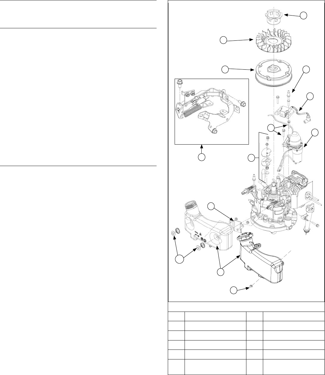
50
Reassembly
KohlerEngines.com 14 690 01 Rev. G
Flywheel/Ignition/Fuel Tank Components
G
H
I
E
L
C
B
K
F
D
J
A
A Screws B Fuel Tank
C Crankcase Bracket D Electric Starter
E Ignition Module F Stud(s)
G Drive Cup H Fan
I Flywheel J Screw(s)
K
Flywheel Brake
Assembly
L Breather Assembly
Install New Spark Plug
1. Set gap of a new spark plug to 0.76 mm (0.03 in.).
2. Install spark plug and torque to 27 N·m (20 ft. lb.).
Install Flywheel Brake Assembly
Dipstick Side of Engine
1. Install spacers onto brake assembly screws.
Fuel Cap Side of Engine
1. Place brake assembly onto engine and loosely
install 2 brake assembly screws.
2. Install a caliper between brake lever and bracket to
establish a 50 mm (1.968 in.) gap, pivoting on rear
screw if necessary.
3. Rotate brake lever clockwise around rear screw.
Torque screws to 9.5 N·m (84 in. lb.). Reinstall kill
lead to ignition module or to bottom terminal on
micro switch (if equipped).
4. Actuate brake arm and verify an audible click is
heard from micro switch (if equipped). Visually
inspect all wires are connected and micro switch is
moving up and down when brake arm is pulled. If an
audible click from micro switch is not heard, loosen
both screws and readjust.
Install Breather Assembly
1. Install breather disc and spring.
2. Install breather screen.
3. Install breather cover and secure with screws.
Torque screws to 10 N·m (88 in. lb.).
A
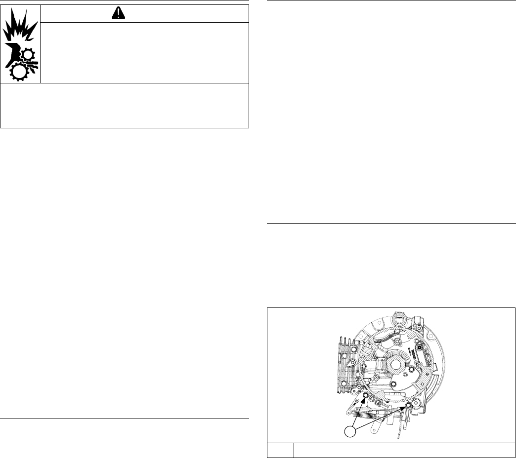
51
Reassembly
14 690 01 Rev. G KohlerEngines.com
Install Flywheel
CAUTION
Damaging Crankshaft and Flywheel can
cause personal injury.
Using improper procedures can lead to broken
fragments. Broken fragments could be thrown from
engine. Always observe and use precautions and
procedures when installing ywheel.
NOTE: Before installing ywheel make sure crankshaft
taper and ywheel hub are clean, dry, and
completely free of lubricants. Presence of
lubricants can cause ywheel to be over
stressed and damaged when mounting nut is
torqued to specication.
NOTE: Make sure ywheel key is installed properly in
keyway. Flywheel can become cracked or
damaged if key is not properly installed.
NOTE: Always use a ywheel strap wrench to hold
ywheel when tightening ywheel fastener. Do
not use any type of bar or wedge to prevent
ywheel from rotating, as these parts could
become cracked or damaged.
1. Install key, into crankshaft keyway. Make sure key is
fully seated.
2. Install ywheel onto crankshaft aligning keyway with
key.
3. Align teardrop slot on fan with raised teardrop on
ywheel. Align drive cup on ywheel, and install and
hand tighten nut.
4. Using a ywheel strap wrench, hold ywheel still
while simultaneously tightening nut to 51.5 N·m
(38 ft. lb.).
Install Electric Starter (if equipped)
Align and mount electric starter onto crankcase. Install
and torque screws to 9.5 N·m (84 in. lb.).
Install Ignition Module
NOTE: If stud for mounting ignition module was not kept
segregated from 2 studs for mounting fuel tank,
compare their lengths and choose short one.
1. Rotate ywheel so ignition magnets are away from
ignition module legs. Position ignition module on
legs with kill tab down.
2. Loosely thread stud and screw into appropriate leg.
Pull module away from ywheel and tighten stud to
hold it in place. Rotate ywheel so ignition magnet is
aligned with module.
3. Set air gap by placing a 0.254 mm (0.010 in.) plastic
feeler gauge between magnet and module. Loosen
stud and let magnet draw module against feeler
gauge. Torque fasteners to 10 N·m (88 in. lb.).
4. Rotate ywheel to release feeler gauge, and check
module does not come in contact with magnet.
Recheck air gap.
5. Connect kill lead to ignition module kill tab.
Install Fuel Tank
1. Secure fuel tank bracket to crankcase by torquing
nut or screw to 8 N·m (71 in. lb.).
2. Secure top of fuel tank to crankcase by installing
threaded studs. Torque studs to 10 N·m (88 in. lb.).
3. Install spacers on studs.
Install Flywheel Brake Spring
A
A Brake Assembly Screws
Using a pliers, attach ywheel brake spring onto bracket
hook.
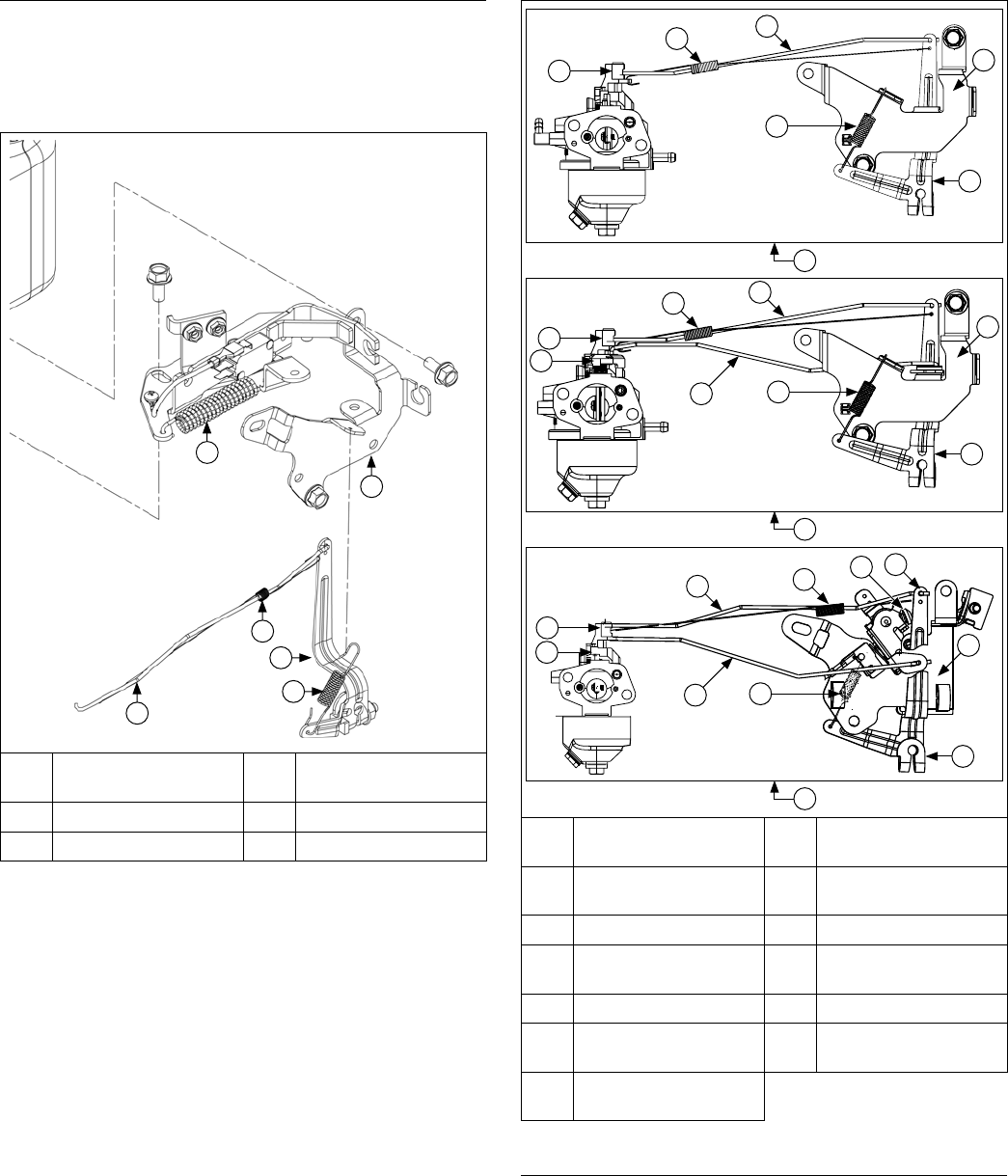
52
Reassembly
KohlerEngines.com 14 690 01 Rev. G
Install Governor Assembly
1. Install governor lever onto governor shaft with lever
up.
2. Attach throttle linkage and linkage spring to top of
governor lever.
Control Components
D
E
F
C
B
A
A
Flywheel Brake
Spring
B
Speed Control
Bracket
C Linkage Spring D Governor Lever
E Governor Spring F Throttle Linkage
Speed Bracket Details
F
E
D
G
I
H
F
J
K
E
D
G
I
H
F
J
K
E
M
L
D
G
I
H
A
B
C
A
Fixed Speed with
Primer (No Choke)
B
Fixed Speed with
Choke
C
Variable Speed with
Choke
D Throttle Linkage
E Linkage Spring F Throttle Lever
G Governor Spring H
Speed Control
Bracket
I Governor Lever J Choke Lever
K Choke Linkage L
Dual Throttle Choke
Control
M
Speed Control
Screw
Install Speed Control Bracket
NOTE: There are 3 different speed bracket variations for
this engine. Images shown identify how different
brackets connect to carburetors with and without
choke.
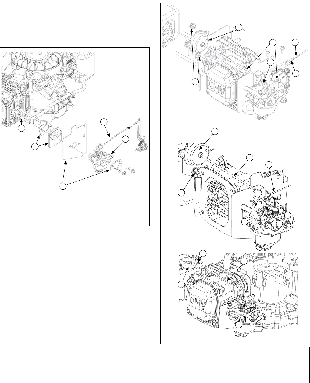
53
Reassembly
14 690 01 Rev. G KohlerEngines.com
Loosely attach speed control bracket to crankcase
using shorter screws. Long screw will be used later for
attaching air cleaner body.
Install Governor Spring
Install governor spring between governor lever and
speed control bracket.
Carburetor Components
D
E
B
A
C
A Carburetor Stud(s) B
Gasket and Spacer
Kit
C
Gasket and Heat
Shield Kit
D Linkage
E Carburetor
Install Carburetor Gaskets
Place spacer gasket, cylinder head spacer and heat
deector gasket on carburetor studs in order shown.
Install Carburetor and Linkage
NOTE: There are several different ways to attach
carburetor linkage depending on carburetor and
speed bracket used.
Install Carburetor with Primer (if equipped)
1. With carburetor not yet mounted on studs, rotate it
slightly to allow connection of throttle linkage and
linkage spring to throttle lever.
2. Slide carburetor onto mounting studs.
Install Carburetor with Choke
1. With carburetor not yet mounted on studs, rotate it
slightly and slot elbow, at end of linkage, into choke
lever.
2. Connect throttle linkage and linkage spring to throttle
lever on carburetor.
3. Slide carburetor onto mounting studs.
Auto Choke Components
B
C
A
F
E
D
G
E
F
A
H
B
C
A Nut(s) B Arm Assembly
C Linkage D Choke Linkage
E Throttle Linkage F Linkage Spring
G Wire Choke Linkage H Choke Link
B
A
C
H

54
Reassembly
KohlerEngines.com 14 690 01 Rev. G
Install Carburetor with Auto Choke (if equipped)
1. Mount arm assembly onto mufer securing with nuts. Torque to 8.5 N·m (75 in. lb.).
2. Slide carburetor at least halfway onto mounting studs. Connect throttle linkage and linkage spring to carburetor.
3. Connect wire choke linkage while sliding carburetor to its seated position against engine.
4. Insert screws connecting arm assembly to carburetor. Torque to 2.3 N·m (20 in. lb.).
Adjust Governor
Move governor lever away from carburetor to limit of its travel (wide-open throttle), and hold in this position. Do not
stress, ex or distort linkage. Grasp cross shaft with a pliers and turn shaft clockwise as far as it will go, hold and
tighten nut. Torque nut to 9.5 N·m (84 in. lb.).
Reconnect Fuel Line
Slide fuel line tight up against carburetor, and secure connection with a hose clamp.
External Engine Components
F
G
E
D
A
K
C
B
J
H
I
A
Engine Cover and
Insert
B Engine Cover C
Engine Cover and
Retractable Start
D Retractable Starter
E Blower Housing F Mufer Guard G Mufer H Air Cleaner Base
I Breather Hose J Paper Element K Air Cleaner Cover L Precleaner
H
H
J
J
L
L
K
K

55
Reassembly
14 690 01 Rev. G KohlerEngines.com
Install Air Cleaner Assembly
1. Attach primer hose to carburetor (if equipped).
2. Slide air cleaner gasket onto carburetor studs.
3. Slide air cleaner base onto carburetor studs. Attach
base by loosely screwing nuts onto studs, and screw
into crankcase.
4. Attach breather hose to crankcase.
5. Secure air cleaner base by torquing nuts and screw
to 8 N·m (71 in. lb.).
6. Install paper element and foam precleaner (if
equipped) into air cleaner base. Attach air cleaner
cover and hand tighten knob or secure latch.
Install Dipstick Tube (Extended Dipstick)
1. Install dipstick tube to crankcase.
2. Tighten screw to 8 N·m (71 in. lb.).
Install Mufer Assembly
1. Install heat deector gasket onto exhaust mounting
studs, with gasket folds facing cylinder head.
2. Slide mufer onto exhaust studs.
3. Install mufer guard onto exhaust studs and secure
with nuts. Torque to 9.5 N·m (84 in. lb.).
Install Blower Housing
Install blower housing onto studs.
Install Retractable Starter
Place retractable starter onto studs protruding from
blower housing.
Install Engine Cover
Engine Cover (if equipped)
1. Install engine cover and secure it with nuts.
2. Tighten nuts to 8 N·m (71 in. lb.).
Engine Cover and Insert (if equipped)
1. Install engine cover and secure it with nuts.
2. Tighten nuts to 8 N·m (71 in. lb.).
3. Install engine cover insert (if equipped) onto engine
cover, and secure with Torx screws. Tighten to
2.5 N·m (20 in. lb.).
Engine Cover Insert and Retractable Starter (if
equipped)
1. Install engine cover insert and retractable starter and
secure with nuts.
2. Tighten nuts to 8 N·m (71 in. lb.).
Install Fuel Cap
Screw fuel cap tightly onto fuel tank.

56 KohlerEngines.com 14 690 01 Rev. G
© 2014 by Kohler Co. All rights reserved.
